Why Surge Protection is Non-Negotiable for Modern Electronics
A constant supply of electrical power is a minimum requirement in any contemporary electrical system. But this stability is often disrupted by temporary overvoltage events, often referred to as power surges. These bursts of energy, also known as voltage spikes or voltage transients, are of high magnitude and have various sources, such as major events like lightning strikes in the vicinity, normal utility power grid switching processes, or the cycling of heavy inductive loads in a facility. To modern, delicate microprocessor-based electronic devices, a power surge is a destructive phenomenon. Such events can cause instant, irreversible damage or latent damage that results in early failure of sensitive components. In order to counter this widespread menace to electronic circuits, the Metal Oxide Varistor (MOV) has emerged as a common, inexpensive, and essential element in the surge protection industry. This paper will present a technical guide to the MOV, including the theory behind it, circuit design, professional selection criteria, and the key safety considerations that make up a robust strategy for the protection of circuits.
What is a Metal Oxide Varistor (MOV) and How Does It Work?
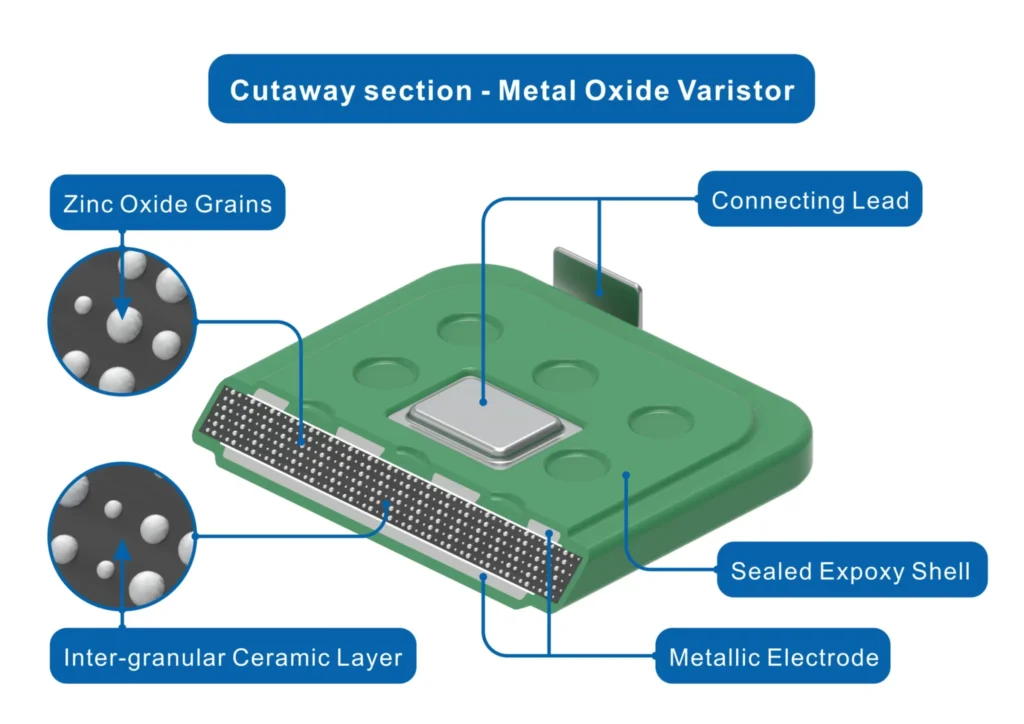
The Metal Oxide Varistor is a basic element of current surge protection technology and is the most common type of varistor in use today. An MOV is a type of varistor, a non-linear type of resistor, characterized by the fact that its resistance changes dramatically and non-linearly with the applied voltage across it. Its construction is primarily a ceramic mass of zinc oxide; microscopically, it consists of individual zinc oxide grains sintered together with a matrix of other metal oxides, often including small amounts of bismuth, to form a complex semiconductor structure. While older technologies used materials like silicon carbide, zinc oxide provides far superior performance.
During normal operation and under normal utility voltage conditions, the MOV exhibits a very high resistance, usually in the mega-ohm (MOmega) range. In this high impedance state, it has a negligible impact on the protected circuit, allowing only tiny current flows (a small leakage current) and permitting power to pass continuously to the downstream load. But when the voltage across the MOV exceeds a certain threshold, as in a transient voltage event, the internal polycrystalline structure of the metal oxide experiences a change in electrical properties almost instantaneously. Its resistance rapidly drops to a few ohms or less, forming a very conductive, low resistance path. This change between a high-resistance and a low-resistance state takes place in nanoseconds, showcasing the MOV’s characteristically fast response time.
The Core Principle: How an MOV Degrades to Protect Your Circuit
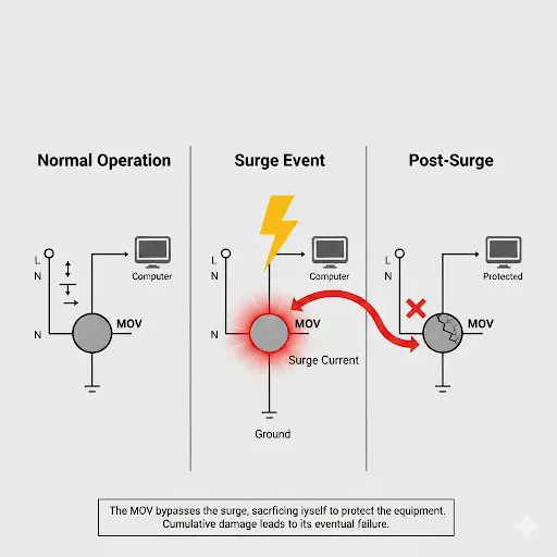
The main purpose of an MOV is not to absorb surge energy, but to bypass it, providing crucial equipment protection. When voltage surges occur and the MOV switches to its low-resistance state, it provides an alternative route for the undesired transient current. Rather than passing into the delicate parts of your equipment, most of the surge current, which can carry significant power for very short durations, is bypassed through the MOV and safely to the neutral or ground line. While conducting this diversion, the MOV absorbs a large portion of the energy of the surge and transforms it into heat. This is a process that is damaging to the MOV in itself; every time it passes a surge, its internal structure is damaged in a small way. This cumulative damage is the trade-off in its operation to safeguard the more valuable downstream circuit.
Visualizing Protection: Understanding the MOV’s V-I Characteristic Curve
The Voltage-Current (V-I) characteristic curve is the best way to understand the behavior of an MOV. This graph is a plot of the current through the MOV versus the voltage across it and is central to its practical use.
- Leakage Region: At normal operating voltages, the MOV is in this region, and a very small leakage current is flowing. The curve is almost flat, signifying that the resistance is very high.
- Knee (Breakdown Region): As the voltage approaches the rated breakdown voltage of the MOV, the curve enters a sharp “knee.” This is the point where the resistance starts to decrease very rapidly, and the device begins to conduct significant current. This behavior is conceptually similar to how a zener diode operates when its diode junction breaks down.
- Clamping Region: During a surge, the MOV operates in this near-vertical region. The voltage across the MOV (the clamping voltage) remains relatively constant even as the surge current through it increases by orders of magnitude. This is the critical clamping effect that holds the voltage across the protected equipment at a safe level, protecting it from excessive voltage.
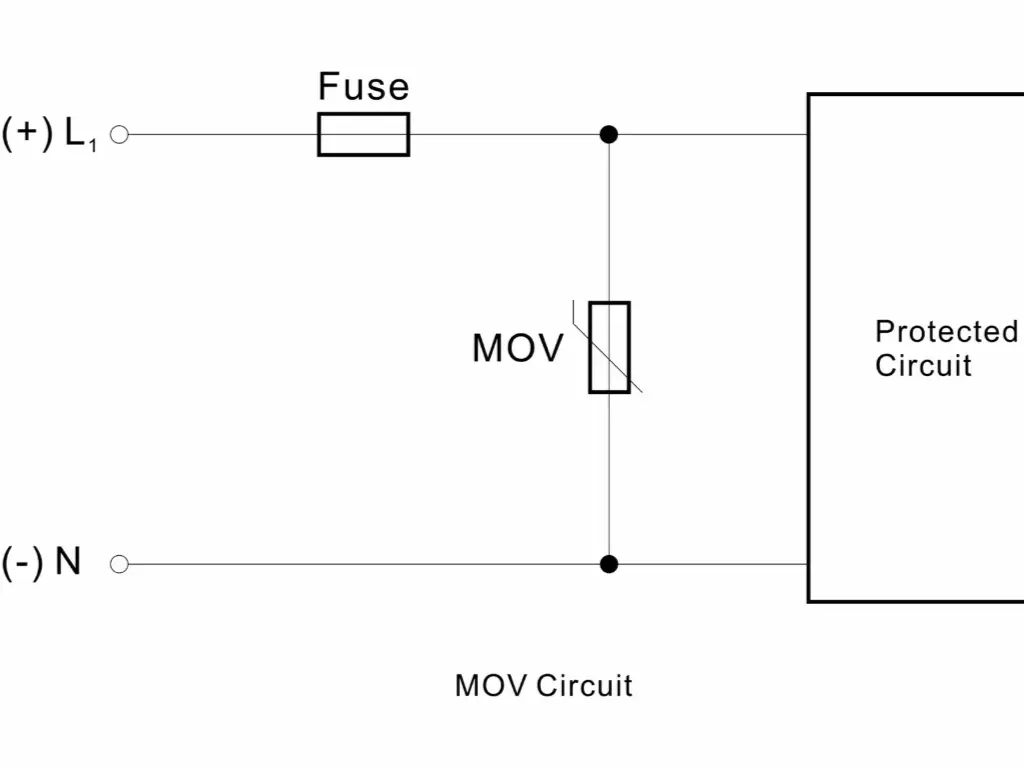
The Fundamental MOV Surge Protection Circuit Diagram
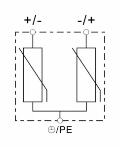
To be effective, MOVs must be placed in parallel with the load they are protecting within electrical circuits. In a typical single-phase AC application, such as on residential power lines or in power supplies, a comprehensive protection scheme addresses surges occurring between any of the conductors. The diagram below illustrates the standard multi-mode protection topology for AC circuits.
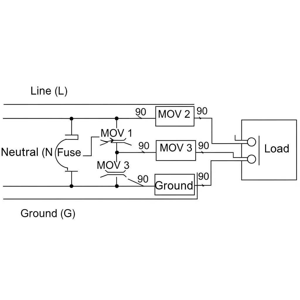
- Line-to-Neutral (L-N) Protection (MOV 1): This MOV safeguards against differential mode surges, which are the most prevalent types of faults occurring between the two main power-carrying conductors.
- Line-to-Ground (L-G) Protection (MOV 2): This MOV guards against common mode surges where both Line and Neutral experience a large voltage spike with respect to the safety ground. This can be caused by lightning or large grid faults, such as the loss of a neutral conductor in a high voltage system.
- Neutral-to-Ground (N-G) Protection (MOV 3): This connection also addresses common mode surges and is essential for safety and preventing ground reference issues in sensitive electronic components used in industrial equipment.
How to Select the Right MOV: A Critical Step-by-Step Guide
The choice of a Metal Oxide Varistor (MOV) is a specific engineering decision. A wrong decision can result in failed protection or create a significant safety risk. It is crucial to respect the component’s absolute maximum ratings. These are the key steps to proper specification.
Step 1: Determine the Maximum Continuous Operating Voltage (MCOV)
The maximum RMS voltage that can be applied to the MOV continuously without it beginning to conduct and degrade is the MCOV. This rating should be greater than the nominal system voltage to allow normal grid variations ( +10% or more ). Choosing an MCOV that is too near the nominal voltage will lead to premature wear and failure.
- – Rule of Thumb: Select an MOV whose MCOV is at least 15-25 times greater than the nominal line voltage.
- – 120 V AC System: In a nominal 120 V AC line, since the average transient or swell voltage can reach 20% (144 V AC) a typical choice is an MOV with an MCOV of 130 V to 150 V.
- – 230 V AC System: A typical MOV choice would have an MCOV (typically shown as UC on datasheets) of 275 V AC, a typical nominal 230 V AC line.
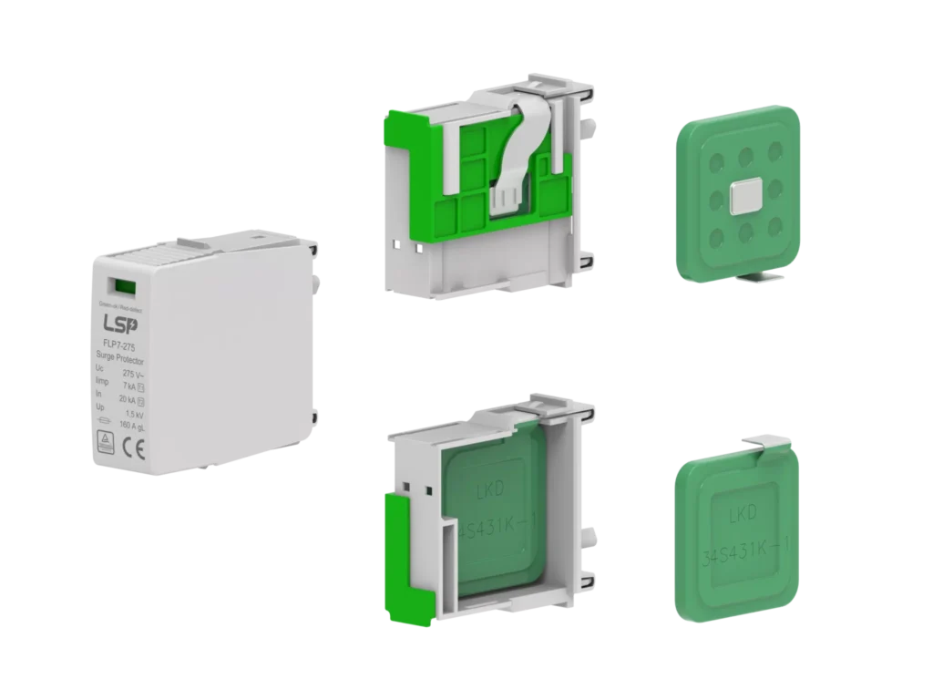
Correlation to Physical Properties: The thickness of an MOV is directly proportional to its voltage rating. The thicker the MOV, the greater the voltage rating.
Step 2: Match the Surge Current (Imax, In) and Energy (Joules) Ratings
These parameters determine the strength and durability of the MOV and directly depend on its physical size. The bigger disc is able to absorb and dissipate more energy.
– Relation to Physical Properties: The greater the surge rating requirement, the greater the MOV diameter must be.
- – e.g. a 20 mm diameter MOV is usually rated at approximately In: 5 kA – Imax: 10 kA.
- – MOVs of 25 mm diameter are usually rated at approximately In: 10 kA –Imax: 20 kA.
- – An Imax rated 34 mm diameter MOV with a 40 kA rating will probably have a rated In at 20 kA.
– Peak Surge Current (Imax): This is the maximum current that the MOV can sustain in one, standardized pulse of 8/20 μs. This should be chosen according to the risk exposure of the application. A service entrance panel may require a 40 kA or higher rating, and a device-level protector may be a 5-10 kA MOV.
– Nominal Discharge Current (In): This is a very important test parameter that shows the maximum current value that an MOV can sustain over a series of repeated surges (usually 15) without any significant degradation. It indicates the durability of the MOV.
– Rule of Thumb: Typically, the In (nominal discharge current) of an MOV is approximately half the Imax (maximum discharge current) rating.
– Energy Absorption (Joules): The energy rating is used to determine the amount of energy that the MOV can absorb throughout its life. The higher the joule rating, the greater or larger the surges that the MOV can handle before it reaches its end-of-life.
Step 3: verify the Clamping Voltage for Your Application
The clamping voltage is the residual voltage that appears across the MOV (and thus your protected load) when it is actively shunting a specified surge current. This is the final and most crucial protection check.
- The Rule: The clamping voltage of the MOV must be less than the maximum voltage the downstream equipment can safely withstand. If the clamping voltage is too high, the surge will still damage your device despite the MOV’s presence.
Guide to Choosing a Specific MOV for an SPD (Practical Examples)
The following illustrate how to find a matching MOV part number in a technical datasheet according to the specifications required by an SPD.
Example 1: MOV for a Type 2 AC SPD
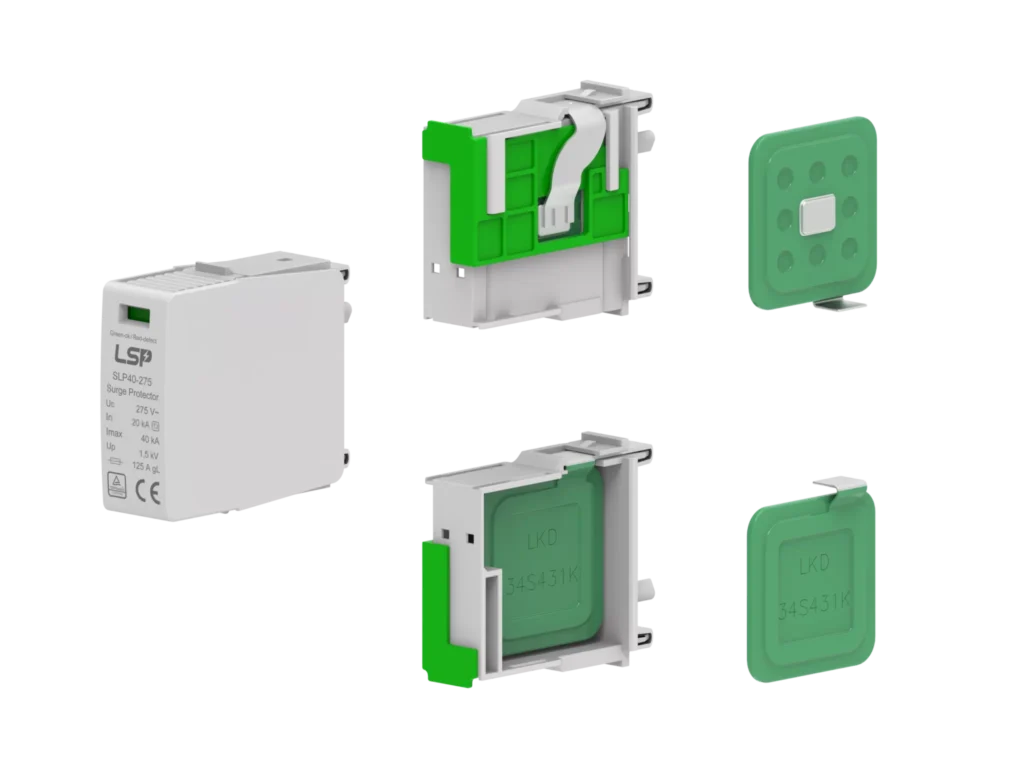
– SPD Model: SLP40-275 series (Un = 230 Vac, UC = 275 Vac, In = 20kA, Imax = 40kA)
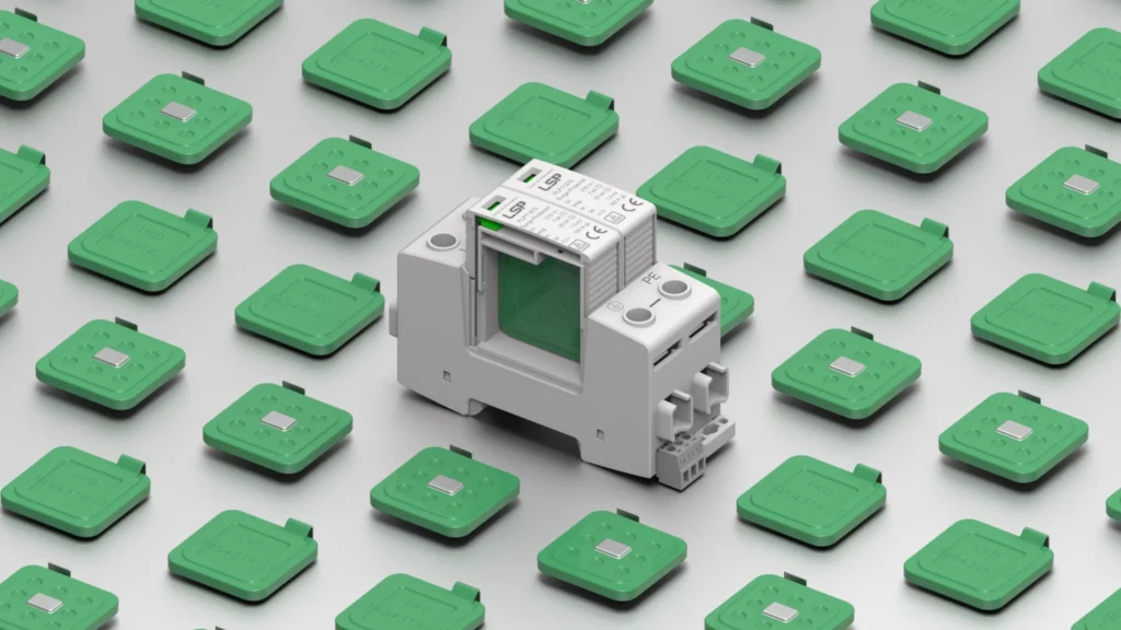
– Process: Obtain the MOV technical parameters PDF (e.g., LKD 34SxxxK Specification). Find the value 275 V by searching the column with Maximum Allowable Voltage (ACrms) or Maximum continuous operating voltage (UC). The corresponding MOV model is 34S431K.
Example 2: MOV for a Type 1+2 AC SPD
– SPD Model: FLP12,5-275 series (Un = 230 Vac, UC = 275 Vac, In = 20kA, Imax = 50kA, Iimp = 12.5kA)
– Process: Download the MOV technical parameters PDF (e.g., LKD 54SxxxK-1 Specification). In the column, search for the term Maximum Allowable Voltage (ACrms) and locate the figure 275 V. The corresponding MOV model is 54S431K-1.
Example 3: MOV of a Type 2 DC SPD (U-Configuration)
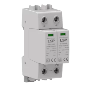
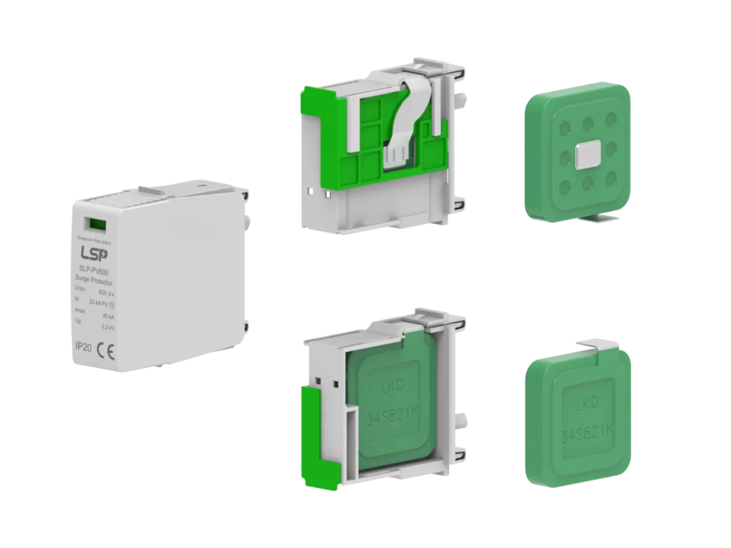
– SPD Model: SLP-PV600 (UCPV = 600 Vdc, In = 20kA, Imax = 40kA)
– Process: Obtain the MOV technical parameters PDF (e.g., LKD 34SxxxK Specification). Find in the column Maximum Allowable Voltage (DC) and locate a value a little higher than 600 V, say 670 V. The corresponding MOV model is 34S821K.
Example 4: MOV of a Type 2 DC SPD (Y-Configuration)
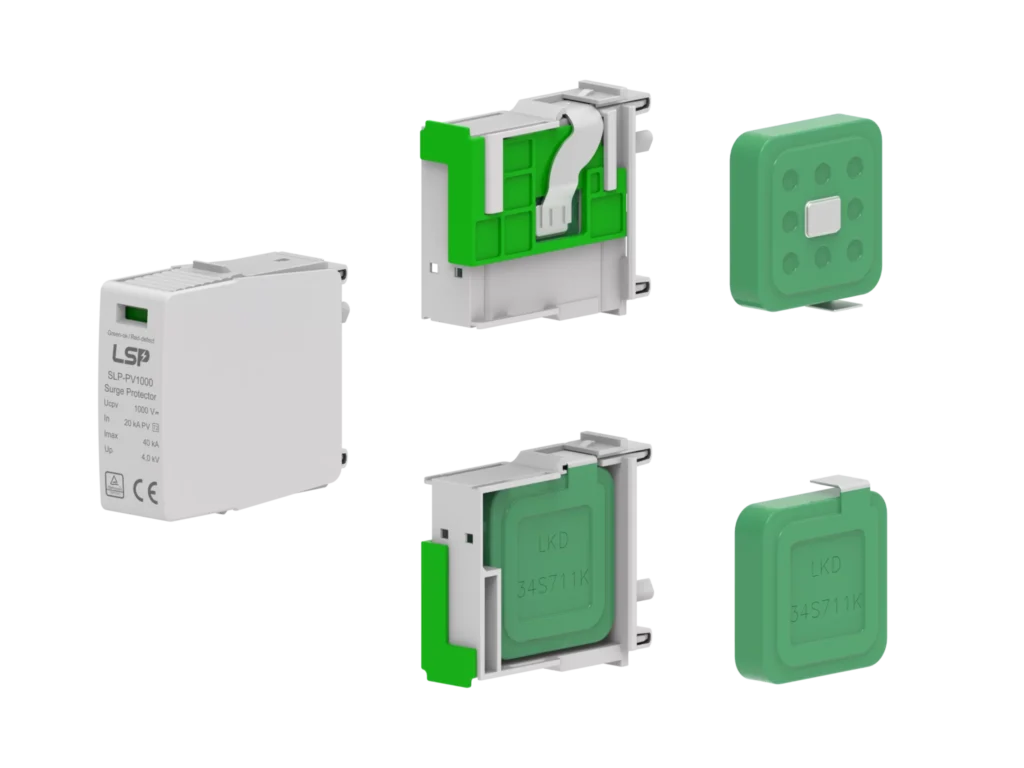
– SPD Model: SLP-PV1000 (UCPV = 1000 Vdc, In = 20kA, Imax = 40kA)
– Procedure: In a Y-connection, the voltage is shared over the MOVs. Get the MOV technical parameters PDF (e.g., LKD 34SxxxK Specification). Find 585 V in the column of Maximum Allowable Voltage (DC). The corresponding MOV model is 34S711K (two would be stacked together to achieve the overall voltage requirement).
The Hidden Danger: MOV Lifespan, Degradation, and Safety Fusing
An MOV is a finite-life component. Every surge it diverts causes a small, irreversible degradation of its internal ceramic structure. Over time, its clamping voltage can decrease, and its leakage current under normal conditions will rise. Eventually, it will reach its end-of-life.
The most common failure mode for an MOV is a short circuit, not an open circuit condition. As it degrades, the increasing leakage current heats the device. This can lead to thermal runaway, where heat generates more current, leading to overheating, smoke, and potentially fire—a catastrophic failure.
To prevent this, it is paramount to install an overcurrent or thermal protection device in series with the MOV. This is a mandatory feature in any professional and safe design.
| Protection Device | Description | Function |
| Fuse | A properly rated fuse will open the circuit if the MOV shorts | Prevents catastrophic failure |
| Thermal Fuse / Thermal Cutoff (TCO) | A temperature-sensitive fuse thermally bonded to the MOV body. If the MOV overheats, it opens the circuit before hazardous temperatures are reached | Directly prevents thermal runaway, offering superior safety |
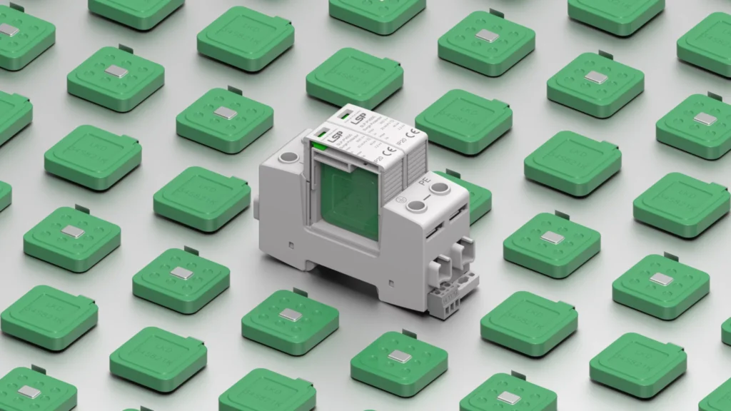
From Component to Certified Solution: The Value of a Professional SPD
As discussed, proper MOV selection, multi-mode configuration, and safe fusing involve complex considerations. An error in MCOV, an undersized joule rating, or omitting thermal fusing can render a protection scheme useless or even hazardous, especially in complex power systems. For mission-critical applications, a proven, integrated solution is far more reliable than a self-assembled circuit.
As a manufacturer dedicated to the research and production of surge protective devices (SPD) since 2010, we understand the complexity behind every step from component selection to the final product. Whether it is the moisture resistance and lightning endurance of MOVs, the precise surge absorption capability of GDTs, the flame-retardant properties of plastic parts, or the corrosion resistance of metal components—any mistake in these details may result in protection failure. That is why we integrate all these design, selection, and safety considerations into our products, providing customers with a verified, complete solution—not just a collection of components.
We also recognize that many customers are often overwhelmed by the complexity of SPD parameters during the selection process. That’s why our team of experts recommends pre-verified SPD modules tailored to your specific application, ensuring perfect performance matching. At the same time, we select LKD brand MOVs—used by global TOP10 SPD manufacturers—and Vactech brand GDTs, trusted by industry giants like Phoenix Contact. With our innovative chamber design, MOVs and GDTs work together to deliver superior surge absorption capability. As a result, our SPDs consistently pass both the 8/20 μs (Type 2) and 10/350 μs (Type 1) waveform tests, ensuring a service life of 5+ years, backed by our 5-year warranty.
Most importantly, our products are not only tested under strict lab conditions—including surge current impact, thermal stability, salt spray, and glow-wire tests—but also fully compliant with the IEC/EN 61643-11 international standard. Furthermore, we are certified by ISO9001, TUV, CB, and CE. These verifications ensure that when customers choose LSP, they receive not only high-quality components but also a fully validated and certified solution, delivering long-term safety and reliability at the system level.
Advanced Strategy: Comparing MOV with TVS and GDT in Hybrid Circuits
For enhanced protection, especially in high-end SPDs, MOVs are often combined with other technologies like Transient Voltage Suppressing (TVS) Diodes and Gas Discharge Tubes (GDTs). Each has unique strengths.
| Feature | Metal Oxide Varistor (MOV) | Transient Voltage Suppressor (TVS) | Gas Discharge Tube (GDT) |
| Response Time | Fast (Nanoseconds) | Very Fast (Picoseconds) | Slow (Microseconds) |
| Energy Capacity | High | Low Voltage, Low Energy | Very High |
| Clamping Precision | Moderate | High (Very Precise) | Low (Voltage Overshoot) |
| Lifespan | Degrades with each use | Generally does not degrade | Very Long, robust |
| Typical Use Case | AC Power Line Protection | Low-Voltage DC, Data Lines | Primary High Energy Diversion |
A hybrid SPD might use a GDT at the entrance to divert the highest energy, an MOV for secondary shunting, and a TVS diode junction for final, fast, and precise clamping right at the sensitive load, providing comprehensive protection from a low voltage data signal to a high voltage input.
Conclusion: Your Next Step Towards Truly Robust Protection
Power surge protection of modern electronics is a basic need to ensure operational stability and asset integrity. We have observed that the MOV is a useful element, but its correct and safe use needs professional understanding of the selection parameters, circuit topology, and critical failure modes. The way to really strong protection is to go beyond individual parts to certified solutions.
This is our value at LSP. Our certifiedsolutions are integrated and not just a collection of parts.
The next thing you need to do is to assess your critical systems and discuss them with our team of experts. Let us deploy a professional SPD strategy for you that provides not just a device, but a complete and reliable method to protect your assets from the inevitability of power surges.