The modern power generation is a direct reflection of a well-designed solar array with its dark solar panels facing the sun in a synchronized manner. Behind this practical look is a system of wires and currents in which electrical power is collected and controlled. When not managed, this combination of energy may be inefficient, chaotic, and even dangerous. It is not a system that you can just put together, it requires accuracy. It needs a frequently neglected, but most essential element: the solar combiner box.
Most would-be solar enthusiasts, who are keen to take up the challenge of self-sufficiency, only think about the high-ticket items, the panels, the inverter, and the batteries that are typical of energy storage systems. The combiner box is often considered as an afterthought, a mere junction box. This is a serious underestimation. A solar array is a combination of several strings of panels, each of which generates an electrical current. The combiner box offers a designed central location to combine these individual currents into one, combined output that is cleanly and safely fed to your inverter. In its absence, you end up with a tangled mess of wires, a state of affairs that causes voltage drop, higher maintenance requirements, and a serious safety risk. This is a guide to people who know that to do a job right is to know all the parts, particularly the ones that give the background functions that are essential. It is a plunge into the why and how of the PV combiner box, including sizing, wiring, and protecting your whole investment in solar power systems.
What is a Solar Combiner Box and Why You Need One
In its simplest form, a solar combiner box is an electrical enclosure that has a simple, but critical, purpose: to combine the output of several strings of solar panels into one, combined output. Once you have more than two or three strings of PV panels, it is impractical and messy to connect all of them to the input terminals of your inverter. The DC combiner box is the main hub, simplifying the wiring and making the whole set of electrical equipment more structured and easy to handle.
However, its role goes much further than mere wire management. The main reason to use a combiner box is to contain overcurrent protection devices (OCPDs), usually fuses or a circuit breaker. The box has a fuse or breaker per string of solar panels. This is a very important safety feature. In the event of a fault on one string, such as a short circuit, which results in a surge of current, the OCPD dedicated to that string will trip or blow, isolating that one string and leaving the rest of the system unaffected. This avoids the fault cascading and possibly damaging the other panels or worse still the inverter, which is usually the most costly single item in a solar installation.
These advantages are threefold:
- Safety: The combiner box increases the safety of the whole PV system by offering a central point of overcurrent protection and a disconnect switch. It reduces the risk of fire and guards your equipment against damaging faults. During an emergency or routine maintenance, the entire array can be de-energized in a safe and quick manner by a single disconnect switch on the combiner box, which lowers the overall maintenance costs.
- Efficiency and Cost-Effectiveness: You can save a lot of material and labor costs by running several strings into one output with a larger gauge wire running to the inverter. It is much more costly to run a dozen smaller wires over a long distance than it is to run one properly sized larger cable, and it causes more line losses (voltage drop). This implies that more of the power you produce is delivered to the inverter.
- Maintenance: In large electrical systems, troubleshooting can be extremely hard and time-consuming when a problem occurs. This is made very easy by the combiner box. Having all the string inputs in one place, it is easy to isolate and test each string separately to identify a faulty panel or connection without having to take the whole array apart.
A combiner box is not merely a suggestion in any grid-tied or off-grid solar system with more than three strings, it is a required safety and reliability component of the National Electrical Code (NEC).
Sizing Your Combiner Box Components Correctly
The choice of the combiner box is not a one-size-fits-all. It must be calculated carefully depending on the particular features of your solar panels and array design. Improper sizing may cause nuisance tripping of breakers, overheating, and a degraded system.
The first step is to decide how many strings your array will contain. The combiner box should have at least as many input terminals as you have strings. It is prudent to select a box that has a couple of additional terminals to allow future growth. Then you need to determine the two most important electrical parameters: maximum voltage and maximum current.
- Maximum System Voltage (Vmax): Check the datasheet of your solar panel to find its Open-Circuit Voltage (Voc). This voltage rises during cold weather. The NEC gives a formula to determine the temperature-corrected maximum voltage. The simplest, but typical, method is to multiply the Voc of the panel by the number of panels in a single series string, and add a safety factor. As an example, a panel with a Voc of 40V and 10 panels in a string, your string voltage is 400V. This may be very high in colder climates. Your combiner box, and all its important parts (fuses, breakers, SPDs) should be rated above your calculated maximum system voltage.
- Maximum String and Output Current: Locate the Short-Circuit Current (Isc) on the datasheet of your panel. This is the highest DC current that a panel can generate. In the case of individual string fuses or breakers, the NEC mandates that they be rated at least 156 percent of the panel ISC (1.25 times continuous operation plus another 1.25 times safety).
Example:
Fuse/Breaker Rating = Isc x 1.56
- In the case of a panel with an Isc of 9A, the calculation would be 9A x 1.56 = 14.04A. Then you would choose the next standard size larger, usually a 15A fuse or breaker.
- The combiner box total output current is the sum of the maximum currents of all the parallel strings multiplied by a safety factor.
Total Output Current = (Number of Strings x Isc) x 1.25
- If you have 6 strings, each with an Isc of 9A, your calculation would be (6×9)x1.25=67.5A. The main busbars, disconnect switch, and the output wiring should all be rated to carry at least this much current. Here you would select components rated at 70A or more likely the next standard size up such as 100A.
- Round to the next standard component size. Cutting corners on these ratings is an invitation to failure. The combiner box is the hub of your array power control; the components used in it should be able to handle the job.
Step-by-Step Solar Combiner Box Wiring Guide
The process of wiring a combiner box is a detailed one that requires care. One loose connection may cause high resistance, heat generation and ultimately, a point of failure. Make sure that the whole system is de-energized before you start.
Prepare Your Equipment & Supplies
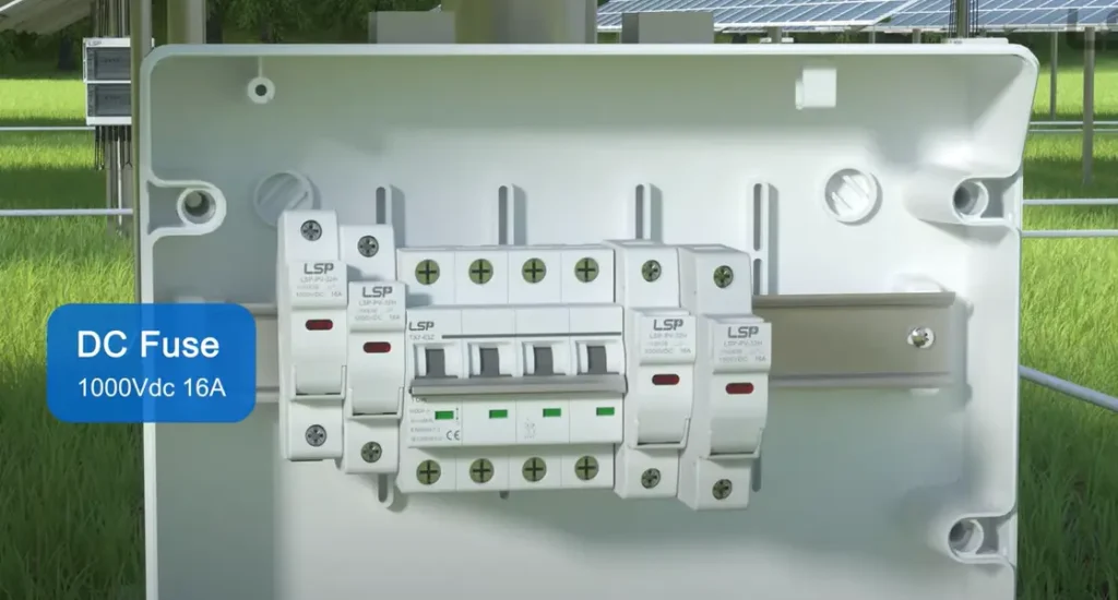
A good wire stripper/cutter, pliers, a set of screwdrivers (including a torque screwdriver to make precise connections), a drill, suitable fasteners to suit the mounting surface, and all your combiner box parts: the enclosure, DIN rail (unless it is already fitted), fuse holders or circuit breakers, positive and negative terminal blocks or a busbar, a ground bar, cable glands (to make sure a watertight seal where wires enter the box), and the appropriately sized wire with suitable connectors.
Install the Enclosure
Select a place that is conveniently accessible yet sheltered against direct and extended sunlight, which may result in excessive heating. Common places are the side of the building or under the eaves. Make sure that it is firmly attached to a solid surface. It is best placed in the middle to reduce the length of the wire runs to the panels, although it is more convenient to place it near the main inverter or controllers.
Solar String Inputs
- Run Wires: Run the positive wires and negative cables of each solar string to the combiner box. Feed the wires into the enclosure through the cable glands, which provide a weatherproof and secure seal.
- Connect Positive Leads: The positive lead of each string is connected to the input of a special fuse holder or circuit breaker. Remove approximately a half-inch of insulation off the wire, push it all the way into the terminal and tighten the screw to the recommended torque as specified by the manufacturer. A hand-tight connection may not be electrically sound; a torque screwdriver is the tool of a professional.
- Connect Negative Leads: The negative leads of all strings are normally connected to a common negative busbar or terminal block. This busbar combines all the negative connections into a single one.
Connect Main Output
After connecting all the string inputs, you will connect the main output which will run to the solar charge controller or inverter.
- Output Positive: There is one, larger gauge wire that is connected to the output side of the fused or breakered busbar (which combines all the positive inputs) and is run out of the combiner box towards the inverter.
- Output Negative: A similar larger gauge wire is connected to the main negative busbar and is run parallel to the positive output wire.
Grounding Your System
Grounding is not a choice, it is a safety precaution that is essential to prevent electrical shock and may help to absorb lightning surges in the vicinity.
- Component Grounding: All metallic, non-current-carrying parts in the box, such as the enclosure itself and the DIN rail, must be connected to the grounding busbar.
- System Ground: The combiner box grounding busbar should be connected to the main system ground, which is usually a grounding rod driven deep into the ground. This gives a safe route to fault currents to flow.
Final Checks & Energizing
Conduct a visual inspection before sealing the box. Ensure that all torqued connections are to specification. Make sure that there are no loose strands of wires that may short out. Check the polarity of all connections-mixing a positive and negative wire can be disastrous and immediate. When you are sure that everything is right, you can seal and close the enclosure. It is only after this that you should go ahead and energize the system, which is usually by switching on the breakers in a certain order as indicated by your inverter manufacturer.
Essential Wiring Diagrams for Common Setups
A wiring diagram is the map of your installation. Although certain arrangements may differ, the basic principles are the same. The most typical arrangement is several parallel strings of series-connected panels.
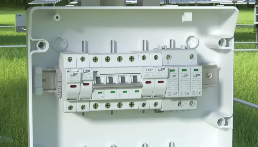
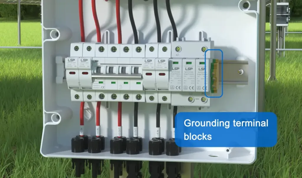
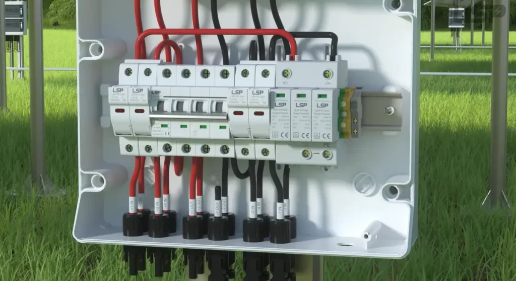
This image shows the physical wiring of a combiner box for a 4-string PV system. The components inside, such as circuit breakers and SPDs, would be represented by symbols in its corresponding schematic diagram.
- Four positive wires of the PV strings coming into the box.
- Every positive wire that ends at a 15A fuse or DC-rated circuit breaker.
The four OCPDs have their outputs linked to a shared busbar.
One, larger positive output wire out of this busbar.
- Four negative PV strings wires into the box.
- The four negative wires all connected directly to a negative busbar.
One, larger negative output wire out of this busbar.
A ground wire between the enclosure and the ground busbar to the earth ground of the system.
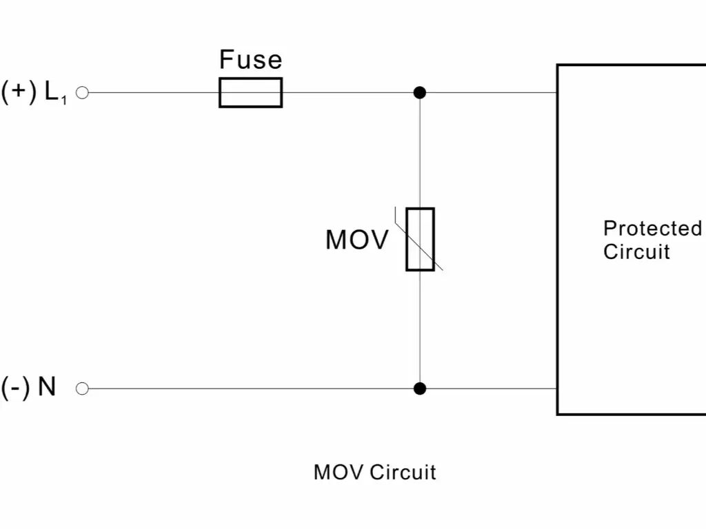
The location of a Surge Protective Device (SPD) will also be indicated in a detailed schematic and is normally wired in parallel between the positive and negative busbars and the ground busbar.
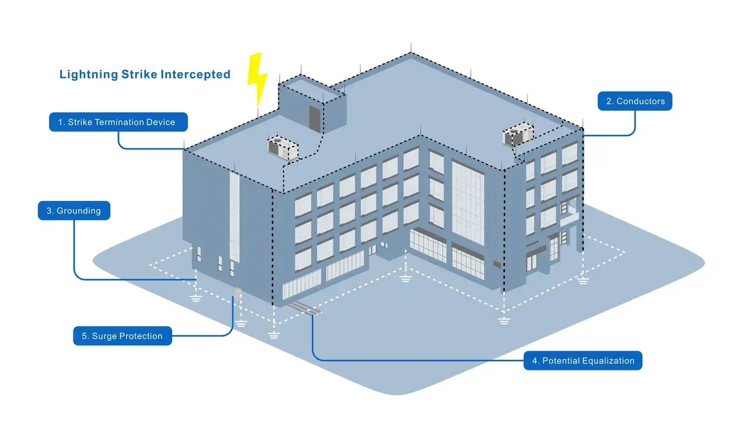
Protecting Your Investment from Lightning & Surges
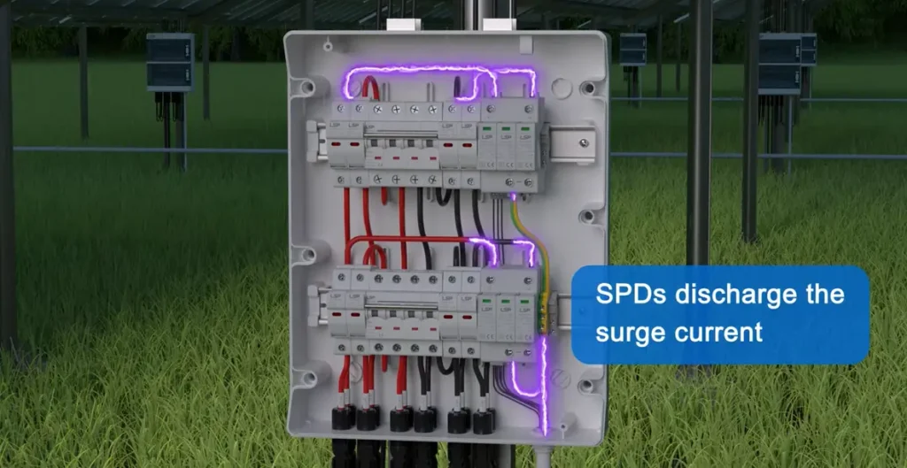
By its nature, your solar array is an exposed electrical system, and therefore vulnerable to atmospheric electrical events. A direct lightning strike is disastrous, and even a nearby strike can cause strong surges into your wiring, which can destroy inverters and other sensitive electronics. The first line of defense is your combiner box, which has the appropriate surge protection.
This protection is based on proper grounding. It provides a low-resistance path to safely divert surge energy into the earth. But grounding is not sufficient. An important addition is surge protection devices (SPDs). An SPD operates by detecting system voltage. When the voltage is normal, it does nothing. However, when it senses a sudden, high-voltage surge, it immediately establishes a low-resistance path to the ground, shunting the damaging energy away before it can damage your equipment. The SPD is intended to take the surge and possibly fail in the process, thus protecting the more valuable components downstream.
To provide full protection, SPDs must be placed on the DC side of the system (inside the combiner box) and on the AC side (at your main service panel).
Why Choose a Professional-Grade SPD like LSP?
Understanding how SPDs work is just the beginning. Choosing the right product is crucial to truly protect your system and your clients’ investments. In real-world solar projects, a failed SPD could lead to inverter damage, costly rework, and customer complaints, which is exactly why many installers and EPC companies choose to partner with LSP.
Since 2010, we’ve specialized in SPD development, and our products meet the IEC/EN 61643-11 standards. Type 2 models can withstand surge impacts of 20kA (±5 times) and 40kA (±1 time). Our encapsulated MOV combined with Vactech GDT ensures stability in humid and high-lightning environments. The housing is made of flame-retardant PA6+GF30% material, and metal components undergo 48-hour salt spray testing to enhance long-term durability. LSP SPDs feature a modular 3+1/4+0 design, making installation easy and quick to replace, which significantly reduces maintenance costs. We also offer 5-year warranty and 12-hour customer support, ensuring every delivery is worry-free.
Don’t let protection be a weak link—choose LSP and make surge protection more professional and reliable.
Common Mistakes to Avoid During Installation
An installation is successful as much by what you do not do as by what you do right. The following are some of the most frequent and expensive errors committed during the installation of solar combiner boxes:
- Incorrect Torque: The most common cause of failure is loose connections. They produce a lot of resistance and this produces heat. This heat may eventually melt the insulation on the wire, destroy the terminals, and cause a severe fire hazard. Apply a torque screwdriver.
- Under-sized Wires/Components: Wires or fuses/breakers that are not rated to handle the maximum calculated current are a sure way to future trouble, whether it is annoying tripping or potentially dangerous overheating.
- Water Ingress: improper cable glands or not sealing the enclosure properly will allow moisture to enter. High-voltage DC electricity and water are a disastrous combination, causing corrosion, short circuits, and ground faults.
- Reversed Polarity: Attaching a positive wire to a negative terminal (or vice versa) will blow fuses immediately and may damage your inverter as soon as the system is energized. Check all connections twice.
- Poor Grounding: A bad or lack of ground connection makes your SPDs ineffective and poses a major shock hazard.
- Neglecting Heat: A sealed combiner box installed in direct, intense sunlight may cause internal temperatures to exceed the operating limits of the components, severely reducing the life of the components. Shade where you can.
The solar combiner box is not another box of wires. It is a basic part of your solar array. It sorts, it safeguards, and it guarantees the safe and efficient distribution of the clean energy you have invested in. Take care of it and it will take care of your system for decades to come.
Bringing It All Together: The Combiner Box as the Linchpin of Your System
We began with a simple premise: a solar combiner box is far more than an ordinary junction box. Throughout this guide, from precise component sizing to a detailed step-by-step wiringguide, we have uncovered its core role as the critical control center of your PV system. It is synonymous with organization, efficiency, and safety, consolidating multiple independent currents into a single, powerful energy stream. Correct wiring, proper torque, and flawless polarity are not just technical requirements; they are the foundation for ensuring your system operates optimally from day one.
More importantly, understanding how to protect your investment and avoid common mistakes is key to transforming a functional system into a durable and reliable asset. A system with poor grounding or lacking a professional-grade Surge Protective Device (SPD) is directly exposed to electrical risks, and its long-term reliability will be significantly compromised. The combiner box is the core location for implementing system protection, providing the first critical node for defending against lightning surges and internal faults. Our mission at LSP is to provide professional-grade SPD products to enhance the protective capabilities of this critical node, ensuring your investment can operate safely, efficiently, and for the long term.