There is an ongoing misunderstanding in the electrical safety discussion: the difference between grounding and surge protection. The other is not an alternative to one system. Electrical protection is a field that has two different disciplines that need to operate in harmony. This guide will debunk this notion by methodically outlining their distinct functions, explaining the differences in how they operate, and outlining their critical, synergistic connection in delivering a truly comprehensive and trustworthy protection system.
The Foundation of Electrical Safety
The most basic safety measure of any well-designed electrical system is grounding, or earthing. It does not serve to safeguard delicate electronics against power abnormalities but rather human life and property against disastrous electrical faults.
A ground connection is a physical connection between the non-current-carrying metal components of the electrical system and the earth. This is done through a ground wire that is connected to a grounding electrode, which can be a long copper rod that is driven deep into the ground. The main role of this connection is to give a low-impedance path that fault current can safely travel to the earth.
When a fault occurs, e.g., a live wire breaks and touches the metal case of an appliance, the electrical current will find the easiest path back to the source. In the absence of a ground wire, a person touching that energized casing may become the primary path, causing severe or fatal electric shock. A much more conductive alternative is provided by the grounding system. The huge amount of current flowing along the ground wire induces a high and fast increase in the amount of current flowing, which in turn trips the respective circuit breakers or blows a fuse, de-energizing the circuit before much damage can be done. Thus, the main goals of grounding are obvious: to avoid electric shock to people and the accumulation of hazardous voltages that may cause damage to equipment or electrical fires. It is the basic, non-negotiable basis on which all other electrical safety precautions are based.
Surge Protection: Shielding Your Sensitive Electronics
Whereas grounding deals with large-scale electrical faults, surge protection deals with another, more insidious risk: transient voltage, more often referred to as a power surge or voltage spike. A power surge is a temporary and large change in voltage in the electrical system. The causes of these events may be numerous. The most spectacular are external events, such as direct or close lightning strikes, which can inject millions of volts into power lines. More typical, though, are internal surges due to the normal functioning of the electrical grid or large appliances in a building (such as HVAC systems or motors) turning on and off.
Such voltage spikes are much too quick and of a different character to be halted by normal circuit breakers. Although they do not present a direct danger of electrocution, they are very destructive to modern electronic equipment. Microprocessors and other sensitive electronics found in the internal parts of computers, televisions, data servers, communication equipment, and renewable energy inverters are built to work within a very narrow voltage range. These components are overpowered by a voltage surge and are damaged irreversibly, or they develop latent failures that drastically reduce the life of the equipment.
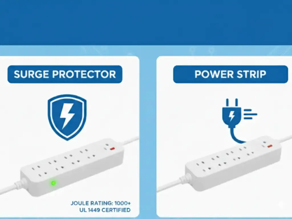
A surge protector, or Surge Protective Device (SPD) is a protective device that is specifically designed to deal with this risk. It is used to continuously check the incoming voltage. It is triggered immediately when it senses a transient voltage above a certain pre-set level, or so-called clamping level, and shunts the excess voltage and any surge current to ground, preventing it from reaching the connected equipment. This diverted energy is safely directed to the grounding system, and the voltage that is fed to the protected device is clamped to a safe value. After the voltage has been restored to normal, the surge protector switches off and goes back to monitoring. It is only there to protect the sensitive internal parts of electronic devices against such harmful, short-duration overvoltage phenomena.
Grounding vs. Surge Protection: Key Differences
To clarify the distinct functions, it is useful to compare grounding and surge protection across their core attributes. While both contribute to overall electrical safety, their roles, mechanisms, and primary targets are fundamentally different.
| Feature | Grounding Protection | Surge Protection |
| Primary Target | Protection of human life from electric shock and property from electrical fires. | Protection of sensitive electronic equipment from damage caused by voltage surges. |
| Working Mechanism | Provides a permanent, low-resistance path to the earth for fault currents, causing circuit breakers to trip and de-energize the circuit. | Detects transient overvoltages and diverts the excess surge current to the grounding system, clamping the voltage to a safe level for connected devices. |
| Core Objective | To safely manage large-scale, sustained electrical faults (e.g., short circuits, ground faults) and prevent immediate danger to people. | To manage very short-duration voltage spikes (transient voltages) and prevent damage to the internal components of electronic devices. |
This comparison makes it evident that these are not competing technologies. Grounding provides the fundamental safety net for the entire electrical system, while surge protection offers a specialized layer of defense for valuable electronics operating within that system.
How They Work Together for Complete Safety
Grounding and surge protection are not just complementary to each other; they are mutually dependent. The surge protector cannot do its job without an effective and properly installed grounding system. The working principle of a surge protector is to redirect undesired, excessive voltage from your sensitive electronics. The million-dollar question is: where does this diverted energy end?
The grounding system is the answer.
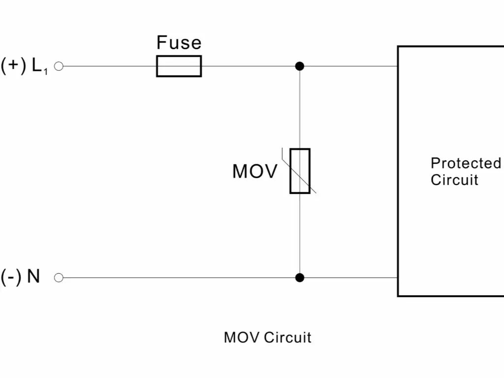
When a surge protector senses a voltage surge, the internal components (usually Metal Oxide Varistors, or MOVs) open like a gate to divert the excess surge current. This current is pushed into the ground wire of the circuit. This high-energy pulse is then directed to the grounding bus of the electrical panel and finally to the earth through the grounding electrode by the ground wire. The Earth is a huge reservoir that can safely absorb and dissipate energy without harm.
This whole process fails without a functional ground path. When a surge protector is inserted into an ungrounded two-prong outlet, or a three-prong outlet with a ground wire that is not connected properly (a frequent problem in older buildings), the surge protector becomes virtually ineffective. In the event of a power surge, the surge protector will then seek to redirect the extra voltage, but there is no route to the earth, so the energy has nowhere to discharge. It can be cut off the hot line, but then it can be forced onto the neutral and ground paths of the equipment itself, which may cause even more damage to the equipment. There is no escape path from the destructive energy that the protective device is attempting to divert.
Selecting Professional-Grade Protection Systems
Achieving comprehensive protection requires a systematic approach. It begins with the foundation—grounding—and builds upon it with a strategically deployed surge protection shield.
Step 1: Auditing Your Grounding Foundation
The grounding system should be checked before investing in surge protective devices. This procedure is not the same with residential users and technical professionals.
A basic audit is simple in the case of residential and general commercial users. Look at every AC outlet that will be used with sensitive electronics. They should be updated to three-prong, well-grounded AC receptacles. The first good sign is the existence of a third round pinhole. A cheap and easy-to-use plug-in circuit tester can be used to verify functionality. These gadgets have a sequence of lights that show whether the outlet is properly wired, such as the presence of a working ground. Any outlet that does not pass this test should be fixed by a qualified electrician prior to using a surge protector.
The audit is much more stringent for technical professionals, such as electrical engineers, panel builders, and infrastructure managers. It goes beyond a mere continuity test to a quantitative measure of the quality of the grounding system. This is done by testing the resistance of the grounding electrode system to earth with special test equipment. Although standards differ by application and jurisdiction, a resistance of 5 ohms or less is a common standard of high-performance systems. Moreover, a professional audit involves checking that equipotential bonding is done correctly, so that all metallic parts of a building (pipes, structural steel, etc.) are at the same electrical potential, and so that a voltage difference between them cannot cause dangerous voltages during a fault or surge event.
Step 2: Layering Your Surge Protection Shield
Having a verified, low-resistance ground connection, the next step is to implement a layered surge protection strategy, commonly known as a cascaded system. It is not enough to use one point-of-use power strip to provide robust protection.
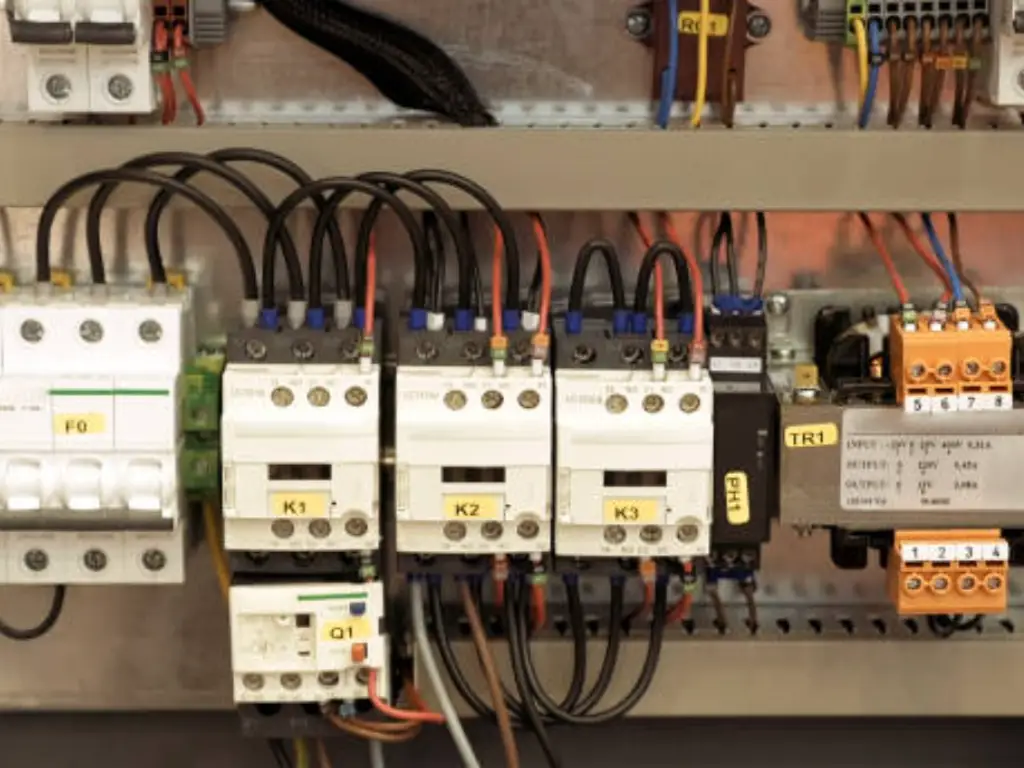
Layer 1: Service Entrance Protection (Type 1 or Type 2 SPD) The first layer of protection is a heavy-duty surge protective device located at the main electrical panel or service entrance.
- Type 1 SPDs are intended to be mounted on the side of the main service disconnect and provide protection against large external surges, such as partial lightning currents. They are necessary in high-risk facilities or facilities with external lighting protection systems.
- Type 2 SPDs are mounted on the roadside of the main service disconnect in the electrical panel. This is the most widely used form of whole-facility protection, which protects the entire electrical system against externally generated surges that propagate down the power line and also against large internal surges.
The main SPD intercepts the energy of a large surge in the vast majority of cases before it can spread across the wiring of the building.
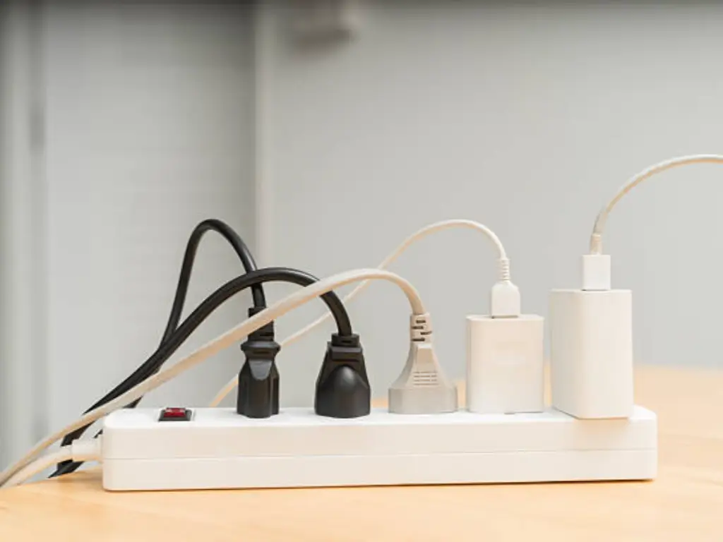
Layer 2: Point-of-Use Protection (Type 3 SPD) The second level is the devices that most people are accustomed to, which include a surge protector, power strip, or a wall-plug surge suppressor. These are Type 3 SPDs. They are intended to safeguard individual items of interconnected equipment against the residual surge energy that can be conducted through the primary SPD, and against locally generated surges. Such delicate protection is essential to delicate electronics. Using both layers, you will have a coordinated system that safely stages the reduction of high-energy transient voltage, so that the voltage that arrives at your equipment is never out of the safe range.
How SPD Tech Interacts with Grounding Systems
To electrical distributors, panel builders, and system integrators, choosing an SPD is much more than a comparison of Imax or Joule ratings. A system match: making sure the internal technology and topology of the SPD are properly matched to the grounding system of the facility is the single most critical decision. A mismatch not only decreases effectiveness but may also undermine the whole safety system and cause nuisance tripping of upstream devices.
The relationship between the SPD and the grounding system is a technical conversation. This is how a professional manufacturer goes through it.
The 4+0 vs. 3+1 Debate: A Decision Driven by Grounding
This is a classic dilemma for anyone designing or supplying systems for global markets. The choice is not a matter of preference but a direct response to the grounding scheme.
- 4+0 Topology (L1/L2/L3/N-PE): In this configuration, all four poles are protected by Metal Oxide Varistors (MOVs) to the Protective Earth (PE). This design is primarily suited for TN-S and TN-C-S systems, where the Neutral and PE conductors are separate and maintain a low-impedance connection.
- 3+1 Topology (L1/L2/L3-PE, N-PE): Here, the three-phase conductors are protected by MOVs, but the critical Neutral-to-PE connection is protected by a Gas Discharge Tube (GDT). This architecture is the professionally specified solution for TT systems, prevalent in many parts of Europe. In a TT system, the facility has an independent earth electrode, and using an MOV in the N-PE path would create a persistent leakage current, inevitably tripping sensitive RCDs. A GDT acts as a high-impedance switch, remaining isolated during normal operation but reliably triggering to divert surge currents when needed.
LSP’s Solution-Driven Approach:
For distributors supplying panel builders in markets with TN systems, our 4+0 models provide a robust solution. For partners in the EU or those building systems for export to TT regions, our 3+1 configuration is essential. This is the kind of detail that comes from over a decade of focusing exclusively on SPD manufacturing.
Specialized Systems, Specialized Interactions
The communication between SPD tech and grounding is even more important in high-value situations.
- To PV & ESS Manufacturers: Photovoltaic arrays are DC systems and may be either grounded or floating (ungrounded). A professional DC SPD, such as the dedicated PV series of LSP, is designed to operate to 1500V DC and generally employs a Y-type of MOVs and a GDT to safely dissipate fault conditions in either system type, to protect the inverter.
- Telecom (5G Base Stations) & Infrastructure: These sites require maximum uptime. The N-PE component of a 3+1 SPD cannot be compromised. LSP only uses Vactech brand GDTs and LKD brand MOVs to ensure performance, and screens them to a tight tolerance of +/- 10 percent. This component-level quality control is what makes our industrial automation and telecom partners rely on predictable, reliable performance.
For Professionals: Sourcing & Partnership Insights
To equipment manufacturers, distributors, and engineering firms, the selection of an SPD supplier is a strategic move that influences the product integrity, supply chain stability, and market reputation. The correct partner not only offers a component, but also technical know-how and logistical dependability.
Customization and OEM/ODM Capabilities: Off-the-shelf, standard products do not suit all technical or branding needs. An excellent manufacturing partner will provide full OEM/ODM services. We collaborate with your engineering teams directly at LSP to create bespoke SPD solutions. This can range all the way to having the product privately labeled with laser-engraved logos and custom packaging to developing proprietary designs on a full scale. We have an in-house design team that can supply 3D models and renderings to help with your marketing and can help you obtain TUV, CB, and CE sub-certifications, which can greatly reduce the time-to-market of your product.
Supply Chain Reliability and Flexibility: You should not be limited by the capacity of your component supplier in terms of production. LSP has an annual production capacity of more than 300,000 units on our automated production lines and is able to take on high-volume orders and still provide consistent quality. In the case of standard products, we have a healthy stock of the core components so that we can have a quick lead time of only 10-15 days. More importantly, for companies of any size, we have no Minimum Order Quantity (MOQ) and can be as flexible as possible to our partners, startups, and established businesses.
A Commitment to Quality and Long-Term Support: The dependability of a protective device is most important. We are so confident in our quality that we offer a 5-year warranty. This is a direct consequence of our high-quality control, including 48-hour salt spray tests of all metal components, as well as intense thermal stability and impulse current testing of each batch. Partnership does not end with the sale; our technical team will provide a 12-hour response time to any questions and can offer expert advice on product selection, installation, and troubleshooting. We are not only suppliers, but your long-term electrical protection partner.
A Quick Safety & Protection Audit
This last checklist will help you conduct a simple audit of your electrical safety system. By taking care of these considerations, you will be much safer not only in terms of immediate electrical hazard but also in terms of long-term equipment damage. Understanding overload protection vs surge protection ensures you cover both short-term risks and lasting safety needs.
Grounding Checks:
- [ ]Visual Inspection: Do all outlets that are used to plug in valuable electronics have three-prong receptacles?
- [ ] Simple Test (All Users): Have you used a simple plug-in tester to make sure that your three-prong outlets are actually properly wired and grounded?
- [ ]Professional Audit (Technical Users): Is the resistance to earth of the grounding electrode system measured and verified to be within the specified requirement (e.g., less than 5 ohms)?
- [ ] Connection Integrity: Does the ground wire connection at the main electrical panel look secure and not corroded?
Surge Protection Checks:
- [ ] Layered System: Does it have a whole-facility SPD (Type 1 or 2) at the main electrical panel to act as the first line of defense?
- [ ] Point-of-Use Protection: Is each sensitive electronic device being protected with an individual surge protector (Type 3 SPDs, e.g., power strips)?
- [ ] Status Indicators: Do your point-of-use surge protectors have a protection working indicator light? When the light is off or flickering, then the device has probably given up its life and should be replaced at once.
- [ ] Professional Audit (Technical Users): Does the SPD topology (e.g., 4+0, 3+1) correspond to the building grounding system (e.g., TN-S, TT)?