In the Realm of the Circuit: A Guide to the Distribution Board Diagram
An electrical system that is well-organized works in a silent efficiency. It is an ever-present and essential driver of contemporary life, but its essential elements are usually hidden in plain sight, housed within a consumer unit or panel board. To the professionals involved in the design, installation and maintenance of such systems, the most important document is not the physical hardware, but its schematic representation: the distribution board wiring diagram. This is not just a drawing, it is a comprehensive map of the power distribution, a charter of built-in safety features and the most important tool of an electrical professional.
It is a complicated set of lines and symbols to the untrained eye. This diagram, often called a circuit diagram, is clear to a qualified electrician in terms of the logic of the installation. It shows the protection hierarchy and the exact route that the electrical energy follows from the point of entry to all connected electrical devices. It is a report that conveys vision and thorough planning, which is part of the professional duty of an electrician. Working without it is like working blindly and endangering the integrity of the equipment and the lives of the occupants of the building. This one piece of paper turns a potentially messy and hazardous tangle of live wires and neutral wires into an orderly, controllable, and safe system.
What is a Distribution Board Diagram & Why is it Your Most Important Tool?
The distribution board diagram gives the blueprint for the electrical wiring before any physical installation is done. Essentially, the diagram is a two-dimensional, graphical representation of the distribution board, with all components, all connections, and the intended use of each sub circuit described. It employs a clear and universal language of standardized symbols to convey the manner in which the primary electric supply is subdivided and distributed to other subsidiary circuits, each with its own specific protective devices. The proper wiring of the distribution board is paramount for both function and safety.
This document is significant in that it has three primary functions, namely, installation, troubleshooting, and safety. The diagram is the main instruction manual to the installer. It makes sure that the board is built as per the design, and every protective device is rated and wired to the intended load. It removes ambiguity and makes the construction process standardized. The diagram is a critical diagnostic tool for the maintenance engineer. In the event of a fault or circuit failure, the diagram gives a clear guide to methodical fault-finding, which saves time and minimizes system downtime. It enables the rapid determination of the circuit that is affected and the associated protective device.
Lastly, and most importantly, it is a master document of the safety design of the system. It gives a clear and unambiguous record, which is essential to future upgrades, periodic inspection and testing, and to confirming that the electrical wiring installationmeets all applicable safety standards, such as the National Electrical Code prominent in the US & Canada. It is a statement that the system was designed with safety as the guiding principle. Failure to create or update this diagram undermines the integrity of the installation as a whole. For more information, one might consult a related post or related electrical wiring installation tutorials.
Deconstructing a Standard Distribution Board Diagram: The Key Components
In order to read a diagram, it is necessary to know the role of the parts that make it up. While there are different types of distribution boards, a typical schematic for a phase distribution board is constructed around a few fundamental elements, each with a specific and critical purpose. These are the first steps to becoming fluent in the language of electrical design.
Main Switch (Isolator): The First Line of Control
The Main Switch or Isolator is at the top of the hierarchy of the diagram both graphically and functionally. Often part of a main switch board or main board, this main operating switch regulates the power that comes into the whole installation. It is shown on a diagram as a simple switch with definite ON and OFF positions and its purpose is to isolate the entire distribution board completely off the mains supply. It offers a ‘double pole’ isolation, breaking the connection to both live and neutral conductors at the same time. It is not one of the automatic protection devices; it is a manual control and safety tool used in a case of emergency or for maintenance. The main switch is used to ensure a positive and verifiable break of the main power supply before any work is commenced within the board to ensure a safe working environment.
RCD / RCCB: The Lifesaver for Human Protection
After the main switch in the circuit path we come to a very important safety device, the Residual Current Device (RCD) or Residual Current Circuit Breaker (RCCB). These residual current devices are crucial for human safety. It is symbolized on a diagram by a switch symbol with a test button (‘T’) and a sensitivity rating, usually 30mA. This device is not mainly intended to safeguard electrical appliances, but to safeguard people against hazardous electric shock.
The RCD is based on a principle of current balance. It continuously measures the current entering a circuit via the live conductor and compares it with the current leaving the circuit via the neutral conductor. These two currents are equal in a healthy circuit. When an individual touches a live component, a certain amount of current will pass through his or her body to the ground. This causes an imbalance between the live and neutral currents. The RCD senses this tiny ‘residual current‘ and opens the circuit in a fraction of a second, providing near-instant automatic operation. It cuts off electricity before it can cause severe harm. The sensitivity of 30mA is a very important value because it is lower than the value that is deemed to cause serious damage to the human body.
MCBs: The Guardians of Your Appliances and Wiring
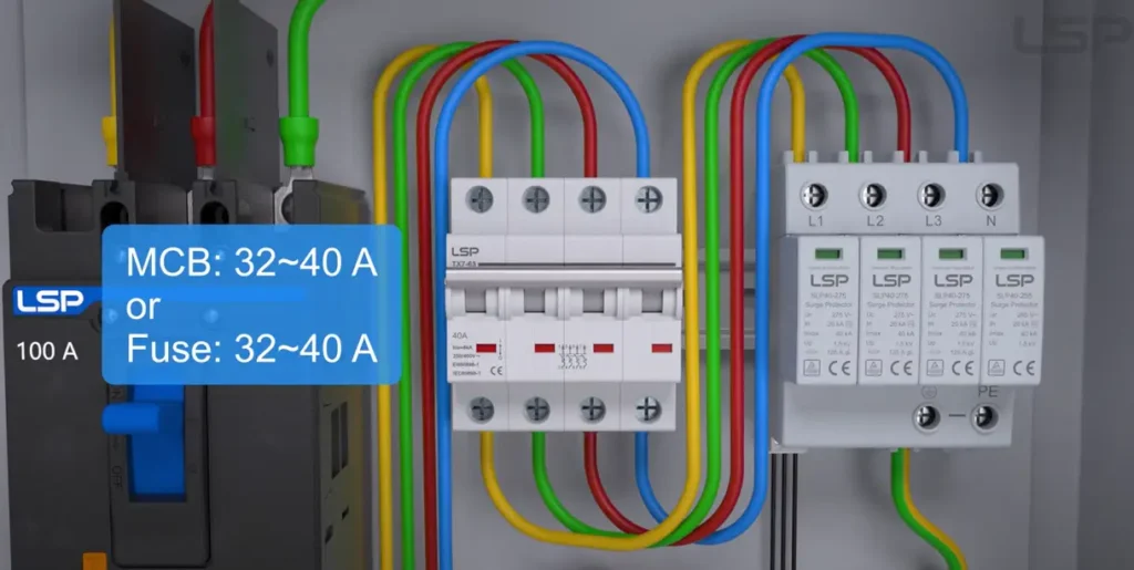
The busbar assembly leads to the individual circuit protectors: Miniature Circuit Breakers (MCBs), a modern replacement for the older fuse board. A symbol that is a combination of a switch, a thermal and a magnetic trip element represents each circuit breaker. These devices offer individual protection to each of the final sub circuits, be it lighting, socket outlets or a high powered appliance. They carry out two protective roles.
To begin with, they offer overload protection. When a circuit is overloaded to cause it to carry more current than the wiring is rated to carry, the bimetallic strip in the MCB becomes hot. It bends as it heats and finally trips the switch, breaking the circuit. This will avoid overheating of the circuit wiring and causing fire hazard. Second, they provide short-circuit protection. A low-resistance fault is a short circuit, which results in a very high and instantaneous surge of current. This sudden surge is sensed by the internal magnetic coil of the MCB and the breaker is tripped almost immediately. This quick action helps to avoid serious appliance and wiring damage to the installation. For a single phase home supply, single pole MCBs are common. MCBs are available with a different rating (e.g. 6A lighting, 32A ring final circuit) and the correctsize of the fuseor breaker is chosen to suit the capacity of the wiring they are protecting.
Busbars, Neutral & Earth Links: The Unseen Foundation
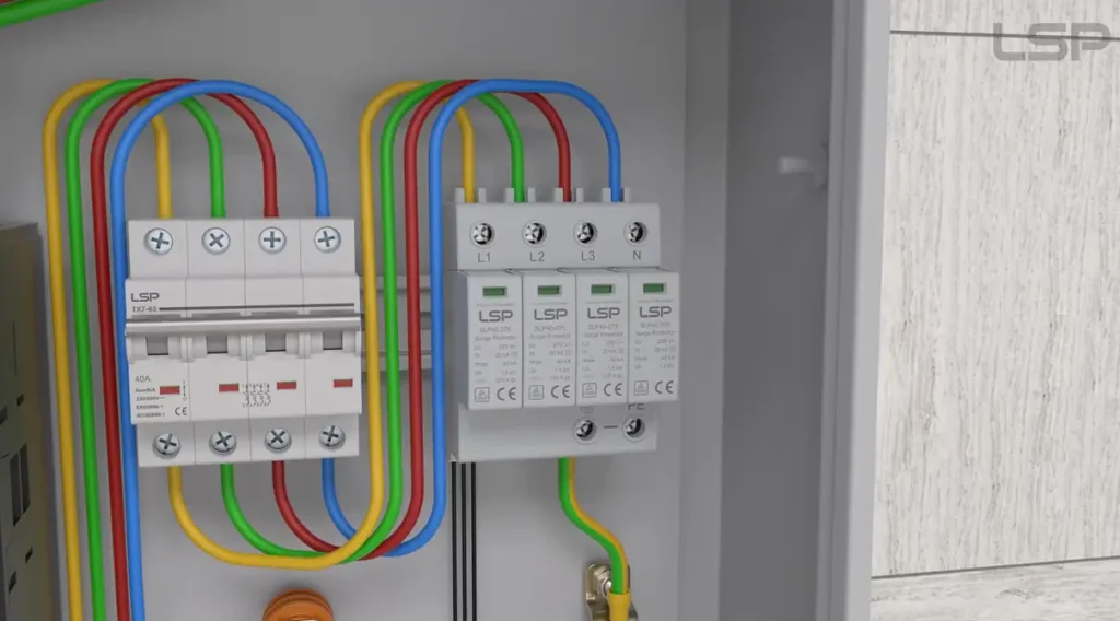
The basic elements of the board are what connect all these components. The busbar, often a common busbar segment, is a solid copper strip, represented by a thick horizontal line on the diagram, which supplies power to the array of MCBs. It takes the primary incoming supply (after the main switch and any upstreamRCD) and gives a common point of connection to the circuit breakers.
The neutral and earth terminal bars are also important and are represented by blocks with several screw terminals. The neutral link offers a shared path of the current of all the individual circuits. The central safety connection point is the earth link, which connects the protective earth conductors of all the circuits to the main earthing terminal of the installation, which is in turn connected to an earth electrode. This special earth connection offers a safe route to fault current flow, which is necessary to ensure that protective devices such as RCDs and MCBs work properly in a faulty situation.
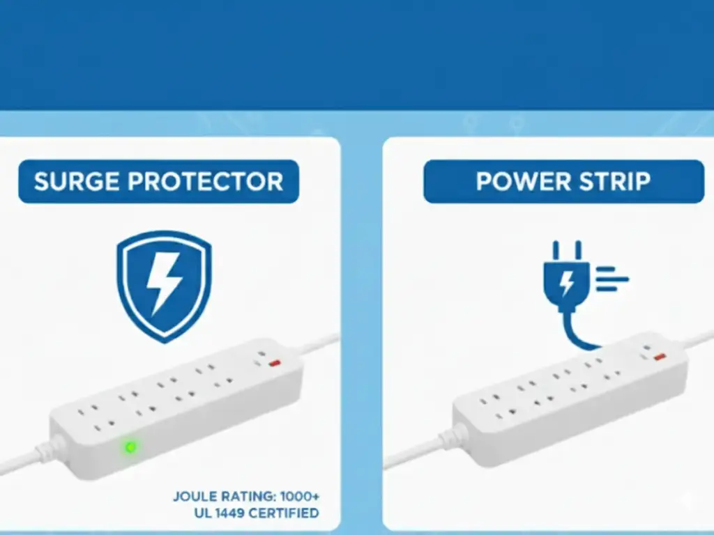
Level Up: Presenting the Advanced Distribution Board Diagram with SPD
A typical distribution board offers good protection against overloads, short circuits and electric shock. Nevertheless, it is not intended to address another major electrical hazard: transient overvoltages, or power surges. They are very short, high-energy voltage spikes that may be generated by lightning strikes far away or switching of large industrial loads on the power grid. In the case of modern buildings that are full of sensitive microelectronicelectrical devices, such surges can result in irreparable damage to thehome supply.
To overcome this threat, the advanced distribution board diagram has a new element: the Surge Protection Device (SPD). Its addition increases the protective abilities of the board, providing an extra defense against external voltage events. This extra element will now be wired into the diagram close to the incoming supply, essentially improving the protective strategy of the whole home supply system, from the main board to a sub distribution board or final distribution board.
The New Element Explained: The SPD’s Role and Placement in the Diagram
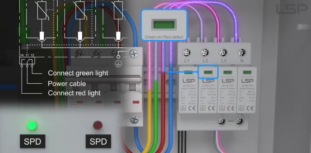
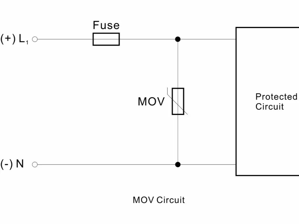
The Surge Protection Device is an electrical safety valve. Its symbol on a diagram is variable, but frequently denotes its fundamental technology, e.g. a varistor or gas discharge tube. It is mainly used to sense a transient overvoltage and during that time, safely redirect the excess surge energy to the earth. This measure avoids the spread of overvoltage through installation and destruction of connected equipment.
The SPD presents a very high impedance at normal operating voltages and does not influence the circuit. As the voltage exceeds a certain activation level, the impedance of the SPD immediately decreases to a very low value. This provides a favorable route to earth, diverting the damaging surge current away from the safeguarded circuits. When the voltage is restored to normal, the impedance of the SPD returns to its high state, and is ready to act again.
The SPD is mounted in parallel with the supply on a diagram. It is installed between the main switch and any RCDs. The live conductor(s), the neutral conductor and the main earth terminal are connected. This location is essential because it enables the SPD to capture surges at the point of entry, thus safeguarding not only the end circuits and appliances, but also the delicate protective devices in the distribution board itself.
Reading Your Advanced Diagram: Tracing the Flow of Power and Protection
Including the SPD, following the circuit on the diagram, one can see a more complete protective system. The power supply, often a single phase supply for a single phase home, originates from a utility pole or electric pole, where the transformer secondary provides the correct voltage. This phase supply travels to the property and first passes through the kwh energy meter (or single phase energy meter). From the energy meter, the service cable brings the power in and the first point of contact inside the consumer unit is the main switch, which offers the manual isolation means. The diagram indicates the parallel connections to the SPD immediately after the switch. This is the initial protective level, which protects against external overvoltages from the secondary of the transformer. The primary current path is then passed on to the RCDs, which offer protection against earth fault currents. Power is fed through the busbar to the individual MCBs through the RCDs. These MCBs guard every final circuit against overloads and short circuits.
The protective logic is organized in layers. Control is provided by the main switch. The SPD offers protection against external voltage surges. The RCD offers individual protection against electric shock. The MCBsoffer protection to wiring and appliances. When reading this advanced diagram, one can see a multi-layered defense strategy, with each element being aimed at countering a particular threat, resulting in a very robust and secure electrical installation. For reliable system performance, it is essential to choose trusted surge protection device manufacturers with proven quality.
From Diagram to Reality: Choosing the Right SPD for Your Board

The conversion of the diagram into a physical installation needs the selection of all the components, including the SPD. The appropriate device is selected on the basis of an evaluation of the geographic location of the installation (lightning risk), the nature of the electrical supply and the level of protection required. SPDs are divided into types.
| SPD Type | Application Scenario | Main Function |
| Type 1 | Installations with high risk of direct lightning strike | Withstand and divert lightning current from direct strikes |
| Type 2 | Most commonly applied in distribution boards | Protect against indirect lightning effects and switching surges |
| Type 3 | At the point of connection with sensitive equipment | Protect sensitive and precision equipment from residual overvoltages |
A Type 2 SPDin the main distribution board is the correct solution to most residential and small commercial properties. Important specifications to note are its voltage protection level (Up), with a lower value representing greater protection, and its nominal discharge current (In).
Why LSP SPDs are the Professional’s Choice
At LSP, we are committed to providing Surge Protective Devices (SPDs) that stand out in the industry. Here’s why professionals choose LSP SPDs, based on our rigorous design and industry-leading features:
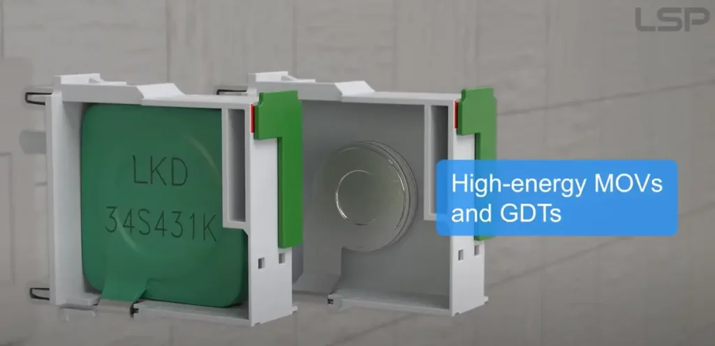
- Engineered for Reliability: LSP SPDs are engineered with superior internal designs and high-quality components to ensure reliability in the most critical moments. Our internal disconnection device, developed over three years, effectively isolates and extinguishes arcs, preventing fire hazards. We use top-tier components like LKD MOVs and Vactech GDTs, both recognized for their durability and performance. These components undergo rigorous testing, including 8/20 and 10/350 waveform tests, to ensure they withstand the toughest surge conditions. With LSP, professionals can trust that our SPDs will reliably protect electrical systems without failure.
- Clear Visual Confirmation: We understand the importance of easy monitoring, which is why our SPDs are equipped with a green board disconnection device that features a clear status window. This allows professionals to visually confirm whether the surge protection is active without needing to open the distribution panel. The window indication, along with the arc isolation and remote indication features, makes it easy to ensure the system is functioning properly, aligning with our goal of clear, “at-a-glance” verification.
- Seamless Integration: LSP SPDs are designed for easy and seamless integration into electrical systems. Our products follow the standard DIN rail design, ensuring they fit perfectly into any distribution panel. With a modular design compatible with 3+1 and 4+0 configurations, our SPDs meet the needs of both European and Chinese markets. Additionally, their compact size and robust build make installation quick and efficient, making LSP SPDs the ideal choice for professionals looking for a reliable and easy-to-install surge protection solution.
Final Safety Principles When Working with Any Distribution Board Diagram
The distribution board diagram is a vital guide, yet the physical equipment that it represents has its own dangers. Electricity should be treated carefully and with professionalism and working on a distribution board is a risky job that can only be done by a qualified person. There are a number of safety principles that should never be neglected, especially when connecting an alternate source like a portable generator.
- First: Isolate and Lock Out. The supply to the distribution board should be de-energized at source before any work is commenced. The isolating switch must be locked in the OFF position and a warning tag must be placed to avoid re-energization.
- Second: Prove Dead. It is not enough to have a visual confirmation of the switch position. To test that there is no voltage between all incoming terminals: line to neutral, line to earth, and neutral to earth, a calibrated, two-pole voltage indicator should be used. This check is required to make sure that the board is safe to touch.
- Third: Appropriate Tools and PPE. Safe practices are necessary even when the power is off. Insulated tools should always be used and Personal Protective Equipment (PPE) should be worn as identified by a risk assessment.
- Fourth: Use the Diagram. Follow the design on the diagram to the letter, paying attention to details like electrical wiring color codes. Do not make unauthorized changes. The diagram is a well-designed system and any deviation may jeopardize its safety and functionality.
- And lastly: Only Competent Persons. Do not do it unless you are qualified and competent to do the work. The distribution board is a key and core component of the electrical system that needs professional expertise to service safely.
Conclusion
A good distribution board diagram is crucial for electrical safety. It must be clear, using standard symbols, and accurate, with precise labels for all circuits and protective devices like MCBs and RCDs, perfectly matching the physical installation.In today’s electronically sensitive world, incorporating surge protection is essential. An advanced diagram including a Surge Protection Device (SPD) represents a shift to active defense, protecting against both internal faults and external grid surges.
Are you ready to provide your system with the professional protection it deserves? Explore our [SPD product series] to find the ideal protective core for your advanced diagram, or [contact our technical team] for expert advice on your selection.