What is a Surge Protection Device (SPD) and Why Are Symbols Important?
Surge protection devices (SPDs) are intended to protect electric systems and equipment from electrical surges caused by lightning strikes, power switching, and faults like short-circuits, which can lead to downtime. Such surges may reach hundreds of volts above the normal operating range, potentially disrupting or even destroying sensitive electronic systems like programmable logic controllers. SPDs reduce the damaging impacts of transient surges by diverting excess energy caused by the surge to the ground. By doing this, the voltage reaching the equipment that needs protecting is lowered, which eliminates the user’s worries and provides peace of mind.
Here are some critical explanations concerning the relevance of symbols. Uniform Interpretation: SPDs provides users with basic understanding poses which makes it easier for non-technical people like engineers, technicians, and even electricians to understand the elaborate design and functionalities of the system. For someone meeting these diagrams for the very first time, these set symbols are very helpful.
- Space Considerations: Another important explanation is the economy of space because these symbols save area when compared to the actual representation of the device. This factor i sof utmost importance with very modern circuit diagrams which have highly complex designs.
- Inter-Language Communication: These circled symbols, unlike the phrases, defy the boundaries of language and geography of regions which are responsible for the maintenance and designing of electrical systems, thus improving the overall amelenge of communication.
- Streamlined Electrical Documentation: The efficiency of wiring diagrams and instructional manuals is enhanced with the use of symbols since documents are more ostensible and contain less text, thus easier to comprehend.
- Safety: SPD symbols when applied and executed accurately to the specified devices guarantees that the devices have been both installed and serviced correctly thus contributing to the safety of the electrical system and increasing the longevity of the equipment being protected.
Understanding the Basic Surge Protection Device Symbol: Key Elements and Standards
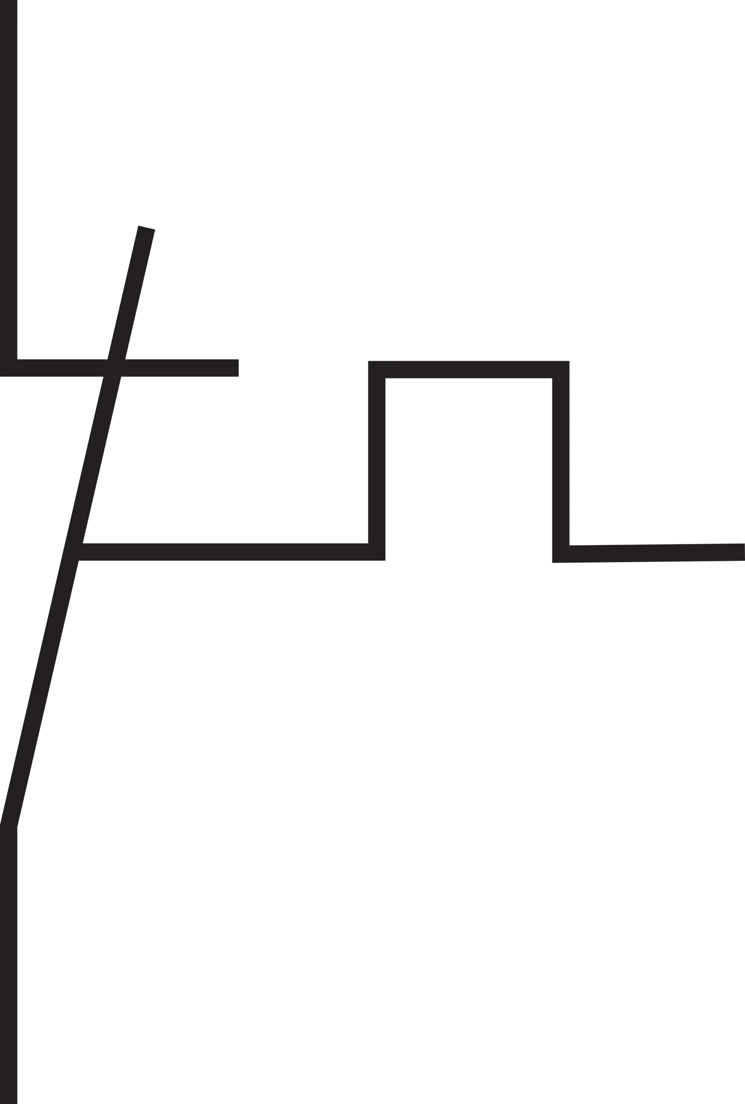
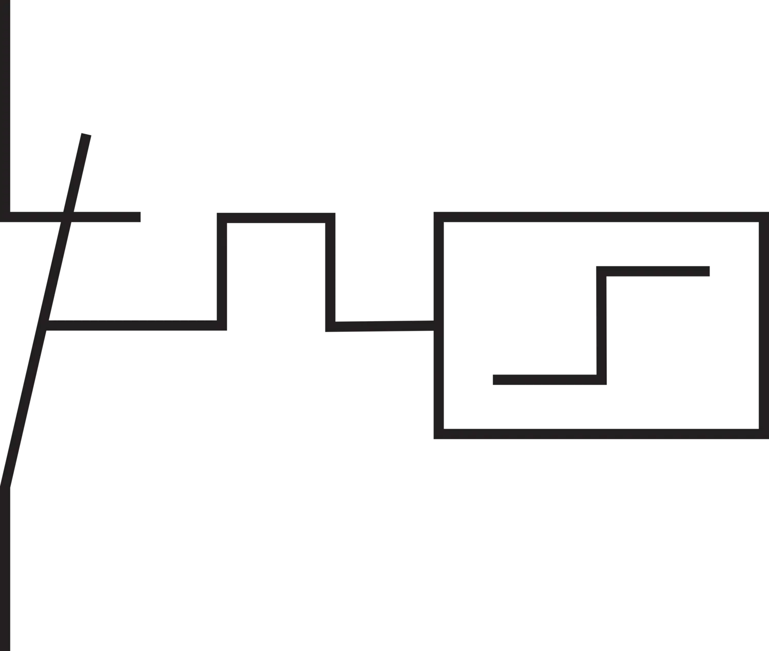
The standard symbol of a Surge Protection Device (SPD) consists of several components that illustrate appropriately the SPD’s characteristic function, which is to channel excess voltage to ground. While some details may differ according to local standards or manufacturers, some details are very much present:
| Symbol/Shape | Description | Function/Meaning | Example in Diagram (Position) |
| Square or Rectangle | Represents the whole SPD device or functional block, sometimes including elements like a thermal fuse. | Denotes the enclosure or unit boundary, which may also indicate built-in safety components. | The dashed-line rectangular boxes enclosing each line and protection element. |
| Protective Element | Depicted as a zigzag line or spark gap symbol, often shown as two opposing arrowheads with a jagged line in between. | Indicates the component responsible for conducting high-voltage surges and protecting the circuit. | Symbols connected to green, red, yellow, blue wires under each phase, representing surge arresters. |
| Ground Connection | Shown as a line running straight down with three short horizontal lines stacked below it. | Represents connection to earth ground, where excess surge energy is safely discharged. | Found below each protective element, directly connected. |
| Input and Output Lines | Multiple lines projecting from the protective element that connect to other parts of the circuit. | Shows the integration points of the SPD into the system, for incoming and outgoing electrical connections. | Top side connections to L1, L2, L3, N (green, red, yellow, blue wires). |
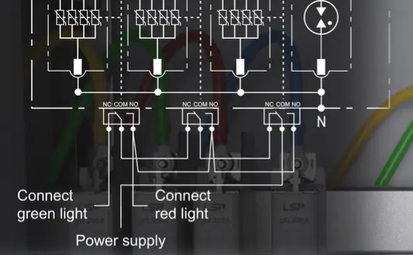
| Status Signal Lines | Relay output terminals labeled “NC, COM, NO”, connected to indicator lights (red/green). | Used for status monitoring of SPD; to control alarm/indicator lights (e.g., green = normal, red = fault). | Found at the bottom part connected to “Connect green light”, “Connect red light”, and “Power supply”. |
Main Features of a Basic SPD Symbol
- Protective Element: Is usually symbolized with a zig-zag break line or spark gap symbol explaining the part that will break during a surge.
- Ground Connection: Is mandatory in locating the surge current safely to the earth.
- Connection Points: Specify the position of the SPD’s insertion within the electrical circuit.
Standards A few international and national standards regulate the symbols of SPDs as well as other electrical diagrams. Some of them are listed below.
| Standard | Description |
| IEC 60617 | A global standard that provides graphic symbols for nearly all electrotechnical diagrams, including surge protective devices. |
| IEEE Std 315 | A standard developed by IEEE that defines USA standard graphic symbols for electrical and electronics diagrams. Organizations like NEMA contribute to its standardization. |
| National Standards | Each country may develop its own national standards, often following international ones. In the U.S., the NEC provides guidelines for electrical installations, including surge protection. |
When using SPD symbols, it is necessary to consult appropriate standards for the area or use of the device for proper understanding. It’s also worth noting that standards evolve, and referring to the latest version, if applicable, is important.
Decoding Different Types of SPD Symbols: Type 1, Type 2, and Type 3 Explained
Surge Protection Devices (SPDs) fall under categories of Type 1, Type 2, and Type 3 according to their placement inside an electrical system and the proportional power of surge current they integrate by dismantling but retaining the essence of protection barriers. Those relate to different values of protection against diverse phenomena such as surges from lightning strikes, switching operations, or even the partial surges that take place when sensitive sensitive pieces of equipment are operative within the boundaries of them.
Overview of SPD Types
Type 1 SPD- These SPDs are strategically placed in main distribution boards abridged toward the electric installation source, typically installed between the secondary of the service transformer and the line side of the service disconnect. They primarily function to receive and safely discharge an extremely high amount of surge current, particularly those arriving from direct or indirect lightning. They will be necessary in the buildings with lightning protection systems (LPS) externally mounted, as they control the management of partial local lightning currents.
Type 2 SPD– Type 2 SPDs are placed in sub-distribution panels downstream of Type 1 SPDs. They allow for the residual primary surges along with surges on account of switching operations to be controlled further. Type 2 SPD is the commonly used device type for widespread protection in commerce and residential electrical installations.
Type 3 SPD– These are located within the closest proximity of the very delicate electronic equipment that needs protection. They offer adequate defense against low-energy leftover surges that may harm delicate devices like computers, household appliances, and industrial control units. Type 3 SPDs are generally deployed together with upstream Type 1 and/or Type 2 SPDs for integrated defense.
Diagrams Representing SPDs and Their Symbols
Although all SPDs share a fundamental symbol, the International Electrotechnical Commission does not distinguish between types of SPDs and assigns a particular graphical symbol for one, which is covered in IEC 60617. Classification is done through text labels adjacent to the symbol e.g. “Type 1 SPD”, “Type 2 SPD” or “Type 3 SPD”. These labels are essential in defining the extent of protection that is most appropriate for a part of the system in question.
While it is not common practice, the internal structure of an SPD (like the number and types of components such as MOVs, GDTs and TVS diodes) is sometimes portrayed in manufacturer specific documents or educational books. Therefore, the symbol as such does not tell anything about the particular components it contains or performance features which it is designed to meet.
Key Points About SPD Symbols and Their Contexts
- Unified Basic Symbol: All SPDs are encompassed under IEC 60617 symbology without differentiation of internal construction for the symbol.
- Importance of Annotations: The specific type of SPD must be shown using textual annotations such as ‘SPD Type 1’ or ‘SPD Type 2’ in a schematic diagram because the graphical symbol does not denote the category of SPD.
- Representation of Components Using Non-standard Symbols: There exist non-standard or company-specific diagrams that may illustrate internal parts such as fuses, thermal disconnectors, or other protective devices. Such representations are, however, not automatic in standardized IEC diagrams and are optional.
- Differentiation Within a Product: Even though the symbol does not indicate it, Type 1 SPDs usually incorporate more robust and higher capacity components such as large MOVs, while Type 3 SPDs have lower power components such as TVS diodes designed for low energy residual surges.
- Compliance to a Standard: The limits of performance, such as the discharge current capacity and the voltage protection levels, are indicated in the document IEC 61643-11 and are accompanied with graphical symbol descriptions in the document IEC 60617.
Final Remarks
While the SPD types do not easily show distinct differences in standard circuit diagrams, the context, annotations, and additional documents assist in differentiating the SPD type captured in the diagrams. Engineers and designers must always check the documents with the labels and specification sheets containing the type of SPD with its location in the system based on the risk and the system protection design requirements.
Key Components Within the Symbol: Varistors, GDTs, and TVS Diodes in SPDs
Having different protective measures against voltage spikes, Surge Protection Devices (SPDs) are usually built with Metal Oxide Varistors (MOVs), Gas Discharge Tubes (GDTs), and Transient Voltage Suppressor (TVS) diodes as the specific components. Surge Protection Devices (SPDs) could range from simple TVS diodes to complex gas tube protectors. The complex designs usually offer better protection than simpler designs which only have MOVs as gas discharge tubes.
It is true that a basic zig-zag line or a spark gap is used to depict the surge protection function in simplified SPD diagrams. Regardless of these symbols that often indicate the function of surge protection, separate components like MWs, GDTs or TVS diodes are not identified which is often the case with surge protective devices. Simplified symbols give no specific details about the defined components but such components are better described in datasheets or detailed documents than in drawings with defined symbols.
| Component | Symbol Description |
 Metal Oxide Varistor (MOV) | 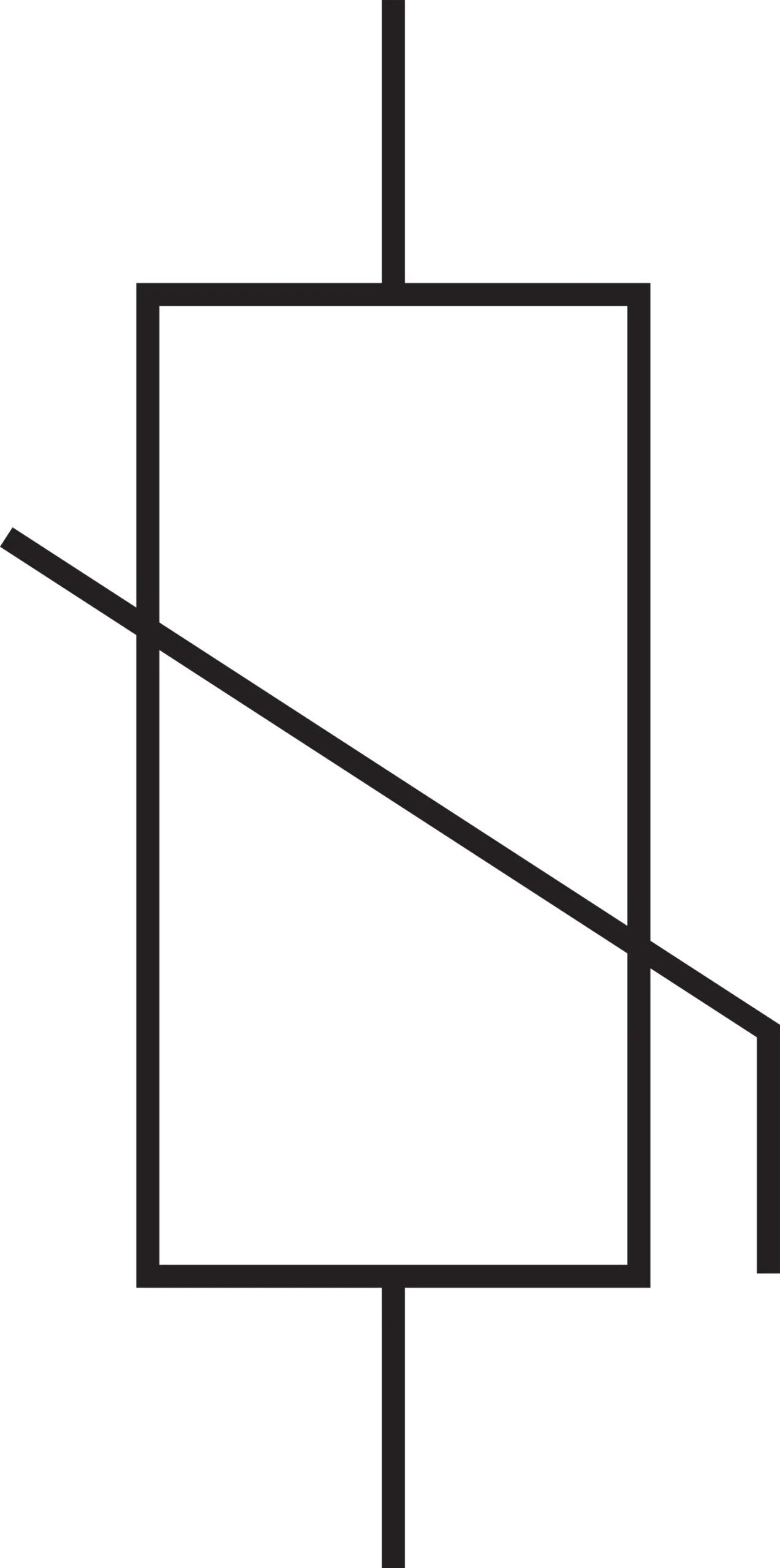 The emblem incorporates a resistor design, which has a diagonal striped line cutting through it to depict its resistance that is dependant on voltage fluctuations. |
 Gas Discharge Tube (GDT) | 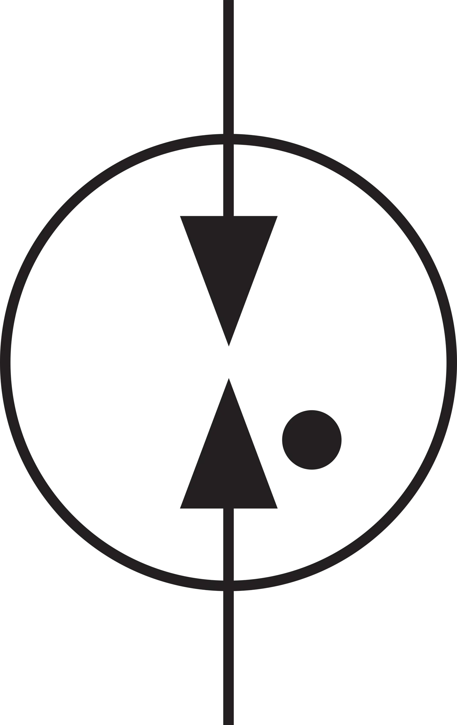 The Zener symbol is formed by two electrodes separated by a small distance and a circle surrounding them, signifying the discharge mechanism which is gas filled. |
 TVS Diodes | 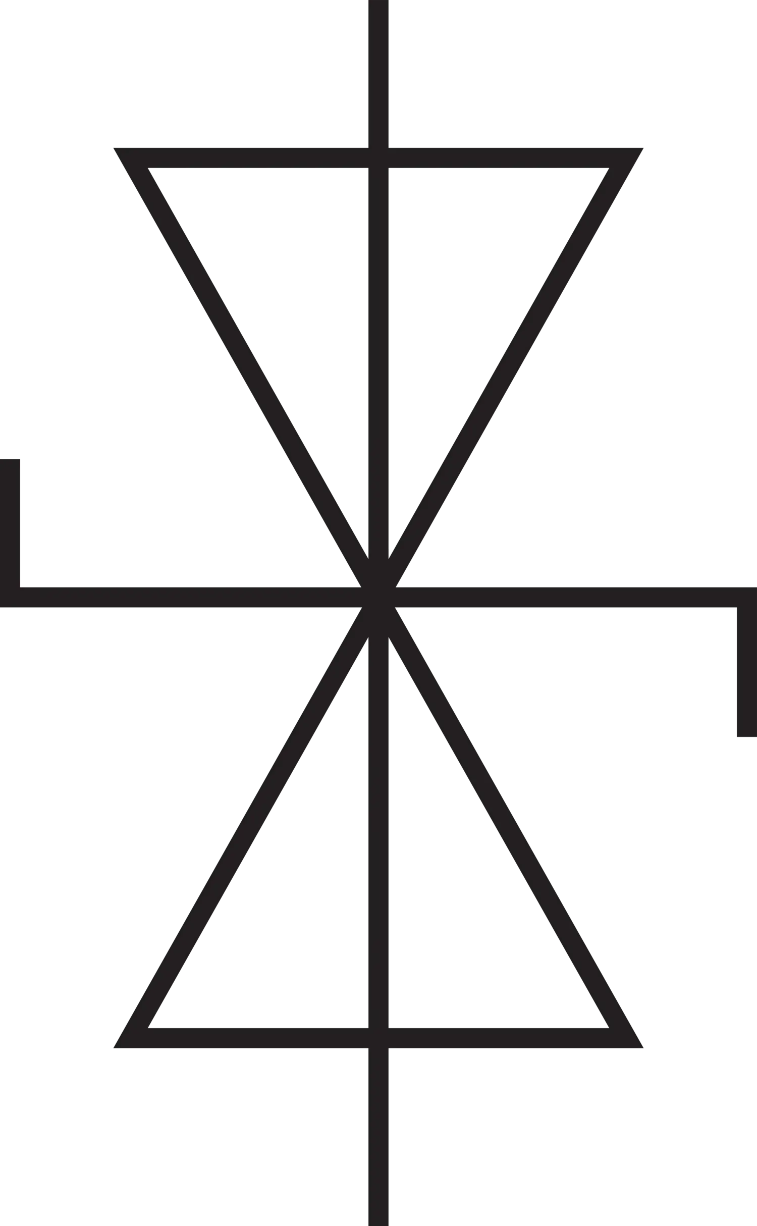 The emblem’s appearance looks like two Zener diodes which are wired oppositely, indicating both uni-directional and bi-directional voltage clamping. |
Below is a more comprehensive set of symbols commonly found in SPD circuits, helping engineers and users identify components easily.
| Symbol | Description |
 Spark Gap | Controlled air gap formed by two triangular electrodes oppose to each other ready for voltage discharge. |
 Horn Gap | Same as spark gap, but has a horn electrode shaped like a dashed circle for efficient guide and extinguish for the arcs. |
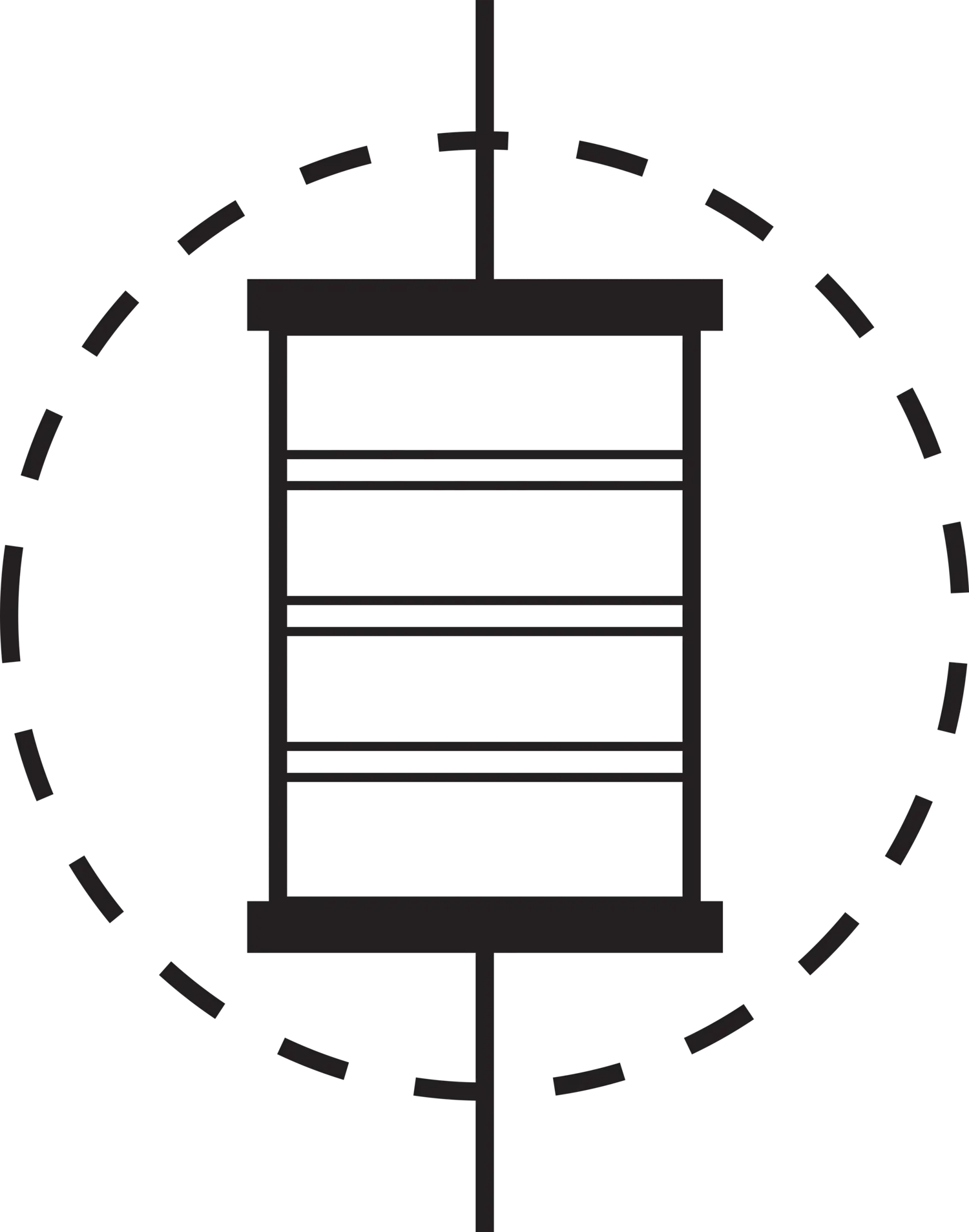 Graphite Spark Gap | A type of spark gap with a dashed circle enclosing it with parallel lines within it representing electrode of graphite for better suppression of arcs. |
 Resistor | A simple box shape icon illustrating resistance realised in a circuit, which limits current flow. |
 Fuse | A rectangle symbol with a single vertical line indicates protective part that will melt when there is too much current. |
 Inductor | Rectangular block shaped filled with black, represent energy store coil used for mitigating transient surges. |
 Thermal Disconnector | As complex symbol made of angluar lines indicating thermally actuated switches that operates after achieving a predefined temperature. |
 Thermo Dynamic Control | A network of interconnected lines and shapes illustrate intelligence system put in charge for the thermal management. |
Socket and Plug Connector | Indicated by a horizontal line and a circle shaped plug on one side and a block on an other side, mark interface for the power output and input connection. |
How these Components Interrelate with the Generalized SPD Symbol? With regard to the basic representations of the circuits, the specific symbol of SPD which is drawn captures the scope of activity performed by one or more of these components. Often the actual technology used in the SPD (MOV, GDT, TVS diode or their combination) is not shown in the corresponding simplified SPD symbol but rather described in the product data sheet or specification documents. For example, the surge suppression system relies greatly on the impedance features of these parts. However, in more advanced diagrams, mostly those which depict the inner circuitry of an SPD, or in aids for instruction, you will probably find these symbols within the contour of the SPD. For instance, an SPD symbol can be made by placing a GDT symbol for first stage high surge protection with MOV symbols for lower voltage clamping. You may even find a symbol of thermal fuse showing extra protection.
Important Considerations
In regard to SPD symbols and their parts, a set of defined practices ought to be followed. These practices make certain that SPDs conform to pertinent standards and offer proper details to engineers and users. In most schematic representations, the legend accompanying the diagram explains what protection methods are implemented (MOV, GDT, TVS diode, etc.). Thus, users can appreciate the full scope of the SPD and its performance under surge conditions.
Practical Applications: Reading and Interpreting SPD Symbols in Circuit Diagrams
Dissecting the SPD Part’s Functionality Within the Picture
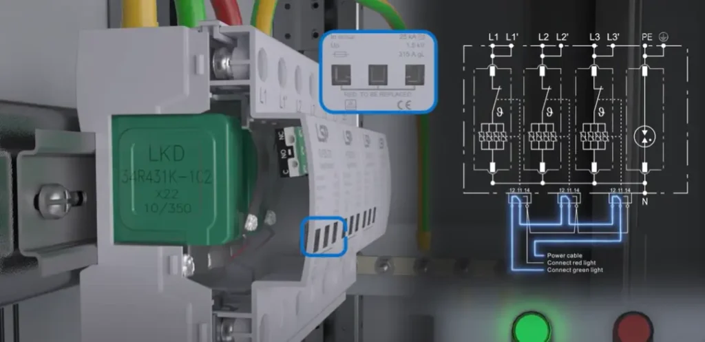
This picture shows a surge protective device (SPD) mounted within an electrical enclosure. It is made for the limitation of transient overvoltage within the system. The green part under the box (or window) marked as ”LKD 34R431K-102” is one of the most important key components, a varistor which interlinks and stores excess energy in the event of a power surge.
The SPD module carries the foremost electrical ratings parts, for instance, discharge current 25 kA (8/20 μs) , Up voltage 1.5 kV, and fuse of 315 A gL, which are ensured to safety Standards to the level necessary. The remaining indication, which is red, may be taken as a substitution monitor. Thus, a monitoring system exists for visual indication of the SPD module performance degradation. The wires that can be seen behind the SPD suggest the presence of additional monitoring contacts (NC/NO) that are commonly associated with remote fault indication.
Understanding the Circuit Diagram for the SPD Device
In relation to the mentioned image, on the left panel, there is a schematic representation of how the SPD is incorporated in a three phase power supply (L1, L2, L3, and PE). The SPD is depicted within a dashed box, showing it being connected in parallel to all three phases and the protective earth (PE), allowing the surge currents to be shunted safely. Understanding the surge protection device working principle helps in appreciating how surge currents are safely diverted through SPD systems. The lower part of the area contains a supervision circuit with auxiliary contacts (terminals 12,11 and 14) for switching the red and green signals. The green light is on when the SPD is in operation; in case a fault happens, such as varistor failure, then the contact is closed, which turns on the red light indicating that servicing is required. This step by step guide allows SPDs to be monitored and serviced effectively while continuously functioning within industrial and commercial electrical systems.
Beyond the Symbol: Key Parameters and Specifications Related to SPD Symbols
Not even the symbol of the Surge Protection Device assists in the selection and implementation of the correct SPD. Important details are usually placed next to the symbol on the datasheets, technical specifications, or even in the diagram and are needed, but not sufficient and relevant. These important details are:
| Parameter Name | Description |
| Maximum Continuous Operating Voltage (Uc or Vmax) | The maximum voltage that can be constantly supplied to the SPD without causing it to conduct. It must be greater than the nominal system voltage. |
| Voltage Protection Level (Up) | The maximum voltage the SPD will allow to pass through to the protected equipment during a surge. Lower Up values are better. |
| Maximum Surge Current (Imax) | The maximum peak current that the SPD can discharge once without failure, typically specified for an 8/20 µs waveform. |
| Impulse Current (Iimp) | Mainly relevant for Type 1 SPDs, indicating the peak current of a specific waveform (typically 10/350 µs) that the SPD can withstand multiple times. |
| Nominal Discharge Current (In) | Defined as the “eighth current from the 8/20 µs waveform that the SPD can discharge 15 times without failure.” |
| Response Time | The time delay before the SPD starts conducting and mitigating the surge. Shorter response times are preferable. |
| Number of Poles | Specifies how many conductors the SPD can protect, such as single-pole (phase-to-neutral) or multi-pole (three-phase). |
| Type of SPD | Categorized into Type 1, Type 2, and Type 3 based on installation location within the electrical circuit. |
| Protection Modes | Defines the voltage transient protection modes, such as line-to-neutral (L-N), line-to-ground (L-G), and neutral-to-ground (N-G). |
| Standards Compliance | The SPD must comply with industry standards like IEC 61643 or UL 1449 to ensure defined performance and safety. |
| Visual Indication | Some SPDs include LED indicators to show operational status. |
| Remote Signaling Contact | Allows status monitoring of SPDs via remote contacts. |
| How Information is Presented | SPD specifications can be found in symbols, datasheets, circuit diagram annotations, and Bills of Materials (BOM). |
Prerequisites towards Fulfilling Implementation As is the case with any other major piece of equipment, an SPD has an operational specification or parameters which must be observed critically with regard to output applications remarks: connecting voltage, power frequency, maximum surge current, Maximum protection level. The approach is prime with an understanding that symbol of surge protective devices SPDs is widely adopted and recognized. In addition to that, the effectiveness of surge protection may be influenced by design parameters and relevant specification. Considerations to the determinants must be given thoughtful assessment.
LSP : Your Expert Partner in Surge Protection – Ensuring Safety and Reliability
As an expert in the field of surge protective devices (SPDs), LSP deeply understands that supply chain and comprehensive strength are the cornerstones for ensuring product safety and reliability. Since 2010, we have been dedicated to the research and development, as well as the production of high-end SPDs, meticulously selecting top-tier global raw materials such as LKD brand MOVs and Vactech brand GDTs, ensuring product performance aligns with the world’s top-tier manufacturers. LSP’s supply chain management is rigorous, with core component screening standards as high as ±10%. Although the lead time without stock is affected by the procurement cycle and takes 2 months, regular products can still be delivered efficiently within 10-15 days.
LSP’s comprehensive strength is reflected in our 1600 square meter factory and two automated production lines, with anannual production capacity of 300,000 units. We hold multiple certifications including ISO9001, TUV, CB, and CE, and possess strong customization capabilities, enabling us to quickly provide customers with personalized products and certification services. With self-developed technologies such as internal tripping, moisture protection, and low-temperature tripping, LSP’s SPDs exhibit excellent performance in lightning surge protection and service life. A strict quality control system, including lightning current impulse, thermal stability, and salt spray tests, along with a 5-year warranty, all demonstrate our commitment to product quality. LSP’s goal is to become a global top 50 brand in the industry, safeguarding your electrical safety with our strength.
Resources for Further Learning: Standards, Guides, and LSP Support
To deepen your understanding of Surge Protection Devices (SPDs) and their symbols, here are some valuable resources you can explore:
To comprehend Surge Protection Devices (SPDs) and their symbols, their explanation comes from the following resources:
- Standards Organizations: Refer to international standards such as IEC 60617 and IEEE Std 315, in addition to national ones offered by ANSI, BSI, and DIN.
- Manufacturer’s The Datasets and Application Notes: Look at manuals and guides from LSP to get information on product symbols and applications documents.
- Educational Resources and Guides: Read available textbooks, take online courses on Coursera, Udemy or YouTube, or read industry magazines for wider coverage on SPD symbols and applications.
- LSP Support: You can visit our YouTube website, speak to knowledgeable people, and receive explicit product and video instruction.
With all these, one is able to appreciate SPD symbols and their importance in engineering system safety and reliability. Remember to always check the applicable standards and documentation from manufacturers for this location and application.