An electrical panel is a vital combination of parts that are enclosed in a box and is the focal point of controlling a machine or an industrial manufacturing process. The quality of its design and construction, requiring careful planning, is a direct measure of the engineering skill that went into it. A panel that is not well organized, with wiring that is not well organized and with components placed in illogical locations, poses a high risk of early failure. On the other hand, a panel that is well thought out, logically laid out, neatly wired, and constructed to the requirements of the environment it is operating in, shows a high level of professional work. This type of design is reliable, safe, and consistent in operation.
This quality assurance is founded on the basic principles of electrical engineering and a comprehensive knowledge of the stresses that a system will be subjected to during its operation. By definition, a professional design is a resilient one. It is designed to not only satisfy the foreseeable requirements of everyday operation but also the electrical abnormalities that may undermine a system. It acts as protection against disruption of operations. In the world of industrial control systems, where the uptime of the operation is directly related to revenue, the quality of the electrical panel is a cornerstone to a successful operation. The goal is not merely to make a working circuit, but to make a system that is safe and provides long-term performance for all industrial equipment.
Introduction: The Mark of a Truly Professional Electrical Panel Design
The electrical panel is a basic element in the industrial automation field. It is the physical embodiment of the control logic of a system, in which power is distributed and machine functions are performed. But there are great differences in the quality of panels. The difference between a crude assembly and a professionally engineered electrical design solution is not in the cosmetic look, but in the resilience of the solution. The professional electrical panel design ensures compliance with all safety criteria and is characterized by its strength—its capability to execute its duties properly throughout its planned life with protection against the electrical hazards that exist in any industrial power system.
This strength is attained by a careful, systematic design process that is focused on safety, meets stringent international standards, and avoids possible points of failure. This design philosophy acknowledges that the integrity of an entire production line may be subject to the proper specification and installation of a single protective element. It is not only the ability to make a system work, but to make it reliable in the long term. That is the mark of a professional industrial control panel builder. This paper will discuss the important aspects of professional panel design, and in particular, one of the most common and destructive electrical phenomena: the power surge. We will examine pertinent international standards, define a clear process of incorporating protective devices, and develop a framework of constructing panels that are not only functional, but designed to be highly reliable.
The Fundamentals: Core Functions and Key Components of an Electrical Panel
*This video explains all the parts of an electrical panel.
An industrial electrical panel has two main functions. It controls and distributes electrical power and it safeguards the equipment and the personnel against electrical hazards. A better design begins with an understanding of these two roles.
Function 1: Power Distribution and Control
First, the panel is a power distribution center. It takes a main incoming power feed and systematically subdivides, transforms and distributes it to the different loads in the system. The motors, sensors, heaters, actuators, and the control hardware of the system all have power requirements at certain voltages and current ratings. The panel makes this complicated power distribution process orderly and controlled, and it actively guides electrical energy to accomplish certain tasks.
Function 2: Protection of Equipment and Personnel
The second fundamental role is circuit protection and protection. Electrical systems are prone to faulty conditions like short circuits and overloads that may discharge large quantities of destructive energy. The panel is fitted with a system of protective devices that are intended to break these conditions prior to their ability to harm electrical equipment or injure personnel. This is a protective role that is a requirement of any safe and compliant design.
Key Components Every Designer Must Know
The panel designer uses a set of standard components to implement these functions. There are several important devices, often utilized by control panel designers, that are the backbone of almost any modern control panel:

- Programmable Logic Controllers (PLCs): The main control device of the system. The PLC is a computer of industrial grade that runs a stored program. It receives the signals of input devices (sensors, switches) and triggers the output devices (actuators, motor starters) according to its programmed logic. The whole system depends on its dependable functioning.
- Variable Frequency Drives (VFDs): A VFD is a motor controller that is used to control the operating speed of an AC induction motor. A VFD can control the process accurately by adjusting the frequency and voltage to the motor and can save energy. Electrical disturbances are very prone to damage the power electronics of a VFD.
- Circuit Breakers and Fuses: These are overcurrent protection devices. Both serve to interrupt a circuit in the case of an overcurrent condition. A fuse has an element that melts and permanently opens the circuit, whereas a circuit breaker is a reusable mechanical switch. They are chosen depending on the electrical nature of the load and the possible fault current of the system.
- Contactors and Relays: These are switches that are operated electrically. A relay is normally applied to switch lower-power control circuits whereas a contactor is a heavy-duty device applied to switch high-power loads such as motors. They act as the connection between the low-voltage control signals of the PLC and the high-power operating circuits.
- Transformers and Power Supplies: These are the components that do voltage conversion. A control power transformer can step down a 480V supply to 120V to feed control circuits, and a DC power supply will step down AC voltage to 24VDC to feed PLCs, sensors, and other electronic devices. Additionally, it is important to separate AC and DC components to prevent electromagnetic interference.
A professional designer knows the specific role of each part, the limits of its operation, its weaknesses, and the way to combine them to work best and safely.
The Unseen Threat: How Power Surges Undermine Panel Integrity
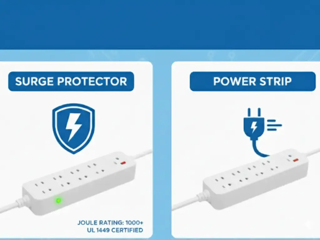
In addition to the familiar hazards of short circuits and overloads, there is a more insidious danger, the transient overvoltage, or power surge. These are extremely brief, high-voltage changes. These transients may be introduced into the power system by events like lightning strikes nearby, switching of large inductive loads in a facility, or switching operations on the utility grid.
Although a large motor might not be sensitive to such a short event, the microelectronic circuits within a PLC or a VFD are highly sensitive. Power surgemay result in immediate and disastrous failure of electronic components, slow degradation that causes premature failure, or logic upsets that halt production. The damage may not be immediate, but may be intermittent or latent failures that are hard to diagnose, weeks or months after the surge event. Shielding sensitive electronics against this threat is an important part of creating a professional-grade panel that can be relied upon.
Navigating International Standards: The Role of SPDs in IEC 61439 & 60204-1

The international standards that regulate professional panel design are safety, reliability, and interoperability. In the case of industrial control panels, two standards are of special concern: IEC 61439, which covers the panel assembly, and IEC 60204-1, which covers the electrical equipment of machinery. While these are key international standards, designers in North America also adhere to standards like UL 508A for industrial control panels.
- IEC 61439 (Low-voltage switchgear and controlgear assemblies): This standard deals with the design and testing of the panel as a whole, ensuring adequate internal space. It defines the conditions under which it must be built so that it can resist the thermal, mechanical and electrical loads of its use, such as its short-circuit withstand capability and temperature rise characteristics.
- IEC 60204-1 (Safety of machinery – Electrical equipment of machines): This standard deals with the use of electrical equipment in a machine, and is concerned with the safety of personnel and the protection of equipment. IEC 60204-1 Chapter 7, “Protection of equipment,” specifically states that equipment must be protected against “overvoltage caused by lightning and switching surges.”
This necessity creates the necessity of Surge Protective Devices (SPDs). The designer should consider and eliminate the risk of transient overvoltages to construct a panel that meets the IEC 60204-1 standard. Although the construction of the assembly is regulated by IEC 61439, the functional requirement of surge protection is prescribed by the application standard IEC 60204-1. A professional designer realizes that these standards offer a clear guideline on how to develop a safer and more reliable system. An SPD is not a feature that can be added or not added to a design; it is a mandatory element of any design that follows the best practices of the international community.
A Step-by-Step Guide to Integrating SPDs (IEC Approach)
The integration of SPDs is a systematic process defined by the IEC 61643 series of standards. This framework guides the proper selection and application of these protective devices.
Step 1: Selecting the Right SPD (Type 1/2/3) based on IEC 61643-11

IEC 61643-11 specifies three main classes of SPDs on low-voltage systems, based on the intended point of installation and energy-handling capability.
- Type 1 SPD: This is the strongest type, which is used to carry the high currents of a direct lightning strike. It is placed at the source of electrical installation, e.g. the main service entrance, to redirect most of the surge energy. A panel at the service entrance of a building that has a lightning protection system would need a Type 1 SPD.
- Type 2 SPD: This is the most common type of SPD used in industrial control panels. It is mounted in sub-distribution boards or in the machine control panel itself. It serves to guard against the residual voltage of an upstream Type 1 device and to reduce surges produced inside the facility itself.
- Type 3 SPD: These devices have lower discharge current capabilities and are applied for point-of-use protection. They are installed in close proximity to very sensitive loads, such as the power supply of a PLC (Programmable Logic Controller). These devices are commonly rail-mounted in control panels and serve as the last line of defense against any remaining transient energy.
The selection is made on the basis of a risk analysis taking into account the lightning exposure of the building, the sensitivity of the equipment and the architecture of the overall electrical system.
Step 2: Universal Best Practices for Placement and Wiring
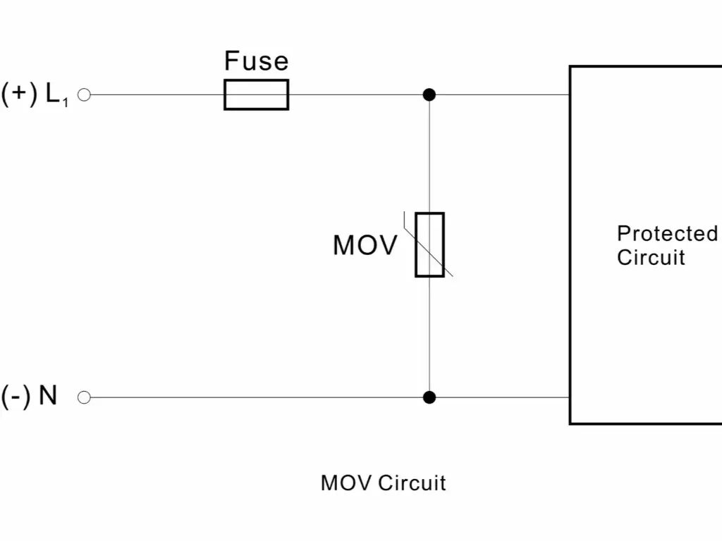
An SPD is very dependent on its installation using cable trays. Its protective capability can be seriously undermined by poor power wiring. The most significant rule is to make the connecting conductors as short and straight as possible.
When a surge occurs, the current passing through the connecting wires of the SPD causes a voltage to be induced across the natural inductance of the wire. This induced voltage is combined with the SPD clamping voltage and the resultant voltage (the voltage protection level, Up) is what the protected equipment sees. Long connecting leads may increase the let-through voltage by hundreds of volts, which may make SPD ineffective.
Thus, the SPD should be installed as near as possible to the point of connection of the circuit (e.g., the main breaker or busbars). The conductors between it and the phases, neutral, and ground should be short, direct, and preferably bundled together to reduce the area of the inductive loop. This is a basic necessity of good surge protection.
Beyond the Component: Choosing a Partner for IEC-Compliant Surge Protection
Since 2010, LSP has been dedicated to the research and manufacturing of surge protective devices (SPDs), with international compliance as the cornerstone of our business. Our complete SPD portfolio is designed and tested strictly in accordance with IEC/EN 61643-11, backed by ISO9001, TUV, CB, and CE certifications. Every unit we produce not only meets demanding performance requirements but also enables our customers to achieve compliance with ease when exporting or entering competitive tenders. With an annual capacity of 300,000 units and a rigorous quality control system, we deliver reliable and high-performing protection for electrical control cabinets, supporting your equipment’s smooth entry into global markets.
Choosing LSP means choosing a partner who deeply understands international standards. Beyond providing SPDs that undergo strict lightning current impulse testing, thermal stability assessments, and long-term durability checks, we also offer customization and certification support tailored to your needs. From early-stage risk assessment and SPD selection to preparing compliance documentation and certification assistance, our team is here to streamline the entire process. With our expertise and proven track record, you save valuable time and certification costs—accelerating product differentiation and global expansion with confidence.
Advanced Protection Strategies: Coordination of SPDs (Cascading)
In buildings that are highly exposed to lightning or where mission-critical equipment is to be protected, a single SPD might not be adequate. A more protective level is offered by a multi-stage protection scheme, called cascading. This includes the installation of a Type 1 SPDat the service entrance, a Type 2 SPD in the distribution panel and a Type 3 device at the point of use.
The success of this system is determined by the electrical impedance (mainly inductance) of the wiring between the cascaded SPDs. When a large surge is introduced into the facility, the upstream Type 1 SPD will activate first and divert the majority of the surge energy. The voltage drop across the conductor between Type 1 and Type 2 SPD permits the downstream Type 2 SPD to operate and dissipate the residual surge energy.
Unless there is adequate length of conductor (usually several meters) between the devices, they will not coordinate properly; the downstream device may be subjected to energy levels above its rating. Correct cascading will result in the protective devices sharing the surge current in a sequential manner with each device absorbing an amount of energy that is suitable to its design. It is a system-level approach that greatly minimizes the final voltage transient observed at the sensitive electronic load.
Conclusion and IEC Design Checklist: Building Resilient Panels

The physical outcome of the physical layout design philosophy of an electrical control panel is its construction. An internationally standard-driven design that is built on the principles of resilience and is highly detailed will result in a better product, which is what machine builders expect. Not only will such a panel carry out its control duties reliably, but it will also be resistant to electrical disturbances, which will guarantee the durability of the equipment and the safety of the personnel.
To do this, the professional panel designer must incorporate the following checklist into his/her workflow:
IEC Design & Surge Protection Checklist:
- [ ] Risk Assessment: Has a risk assessment been carried out to identify the necessity of surge protection as per IEC 60204-1 based on the location and exposure of the installation?
- [ ] Standard Compliance: Does the enclosure and protective devices as well as all other components comply with relevant IEC standards (IEC 61439, IEC 61643-11, etc.)?
- [ ] Proper SPD Selection: Has the proper SPD Type (1, 2, or 3) been chosen according to the risk assessment and the location of the SPD in the electrical distribution system?
- [ ] Coordination (Cascading): In the event that multiple SPDs are employed, is there adequate conductor length and impedance between the SPDs to provide coordination of energy?
- [ ] Short-Circuit Current Rating (SCCR): Does the SCCR of the SPD and its overcurrent protection device (if needed) exceed the available fault current at the point of installation?
- [ ] Optimal Placement: Is the SPD placed as near as possible to the point of connection to the power bus to reduce lead length?
- [ ] Minimized Lead Length: Do the connecting conductors to the SPD have an absolute minimum length, are routed directly, and where possible bundled to minimize additive inductance?
- [ ] Proper Conductor Sizing: Are the connecting conductors of the SPD sized correctly as per the manufacturer and applicable electrical codes?
- [ ] Clear Labeling: Is the panel, and the SPD itself, clearly and permanently labeled as per the requirements of IEC 61439, including warnings and ratings?
- [ ] Detailed Documentation: Does all documentation, such as schematics, component specifications, SCCR calculations, and SPD compliance certificates, exist and accompany the final panel assembly?
In a methodical way, by covering all these points, the designer is involved in the process of engineering a really resilient system, a system that is of high professional standards and offers effective protection against the unpredictability of electrical power.