The distribution board (DB), often called a distribution box or main panel, is a fundamental component of any power distribution system. It serves as the central control point for power distribution, managing the power flow of electrical power from the main supply to all subsidiary or branch circuits. Its proper design and implementation by a licensed electrician are critical for ensuring operational electrical safety, reliability, and the longevity of all connected electrical equipment. This guide outlines a modern approach to distribution board design, emphasizing not only traditional safety measures but also the essential integration of surge protection to meet the demands of today’s electronic-rich environments, from residential buildings to demanding industrial settings.
What is a Distribution Board and Its Core Function?
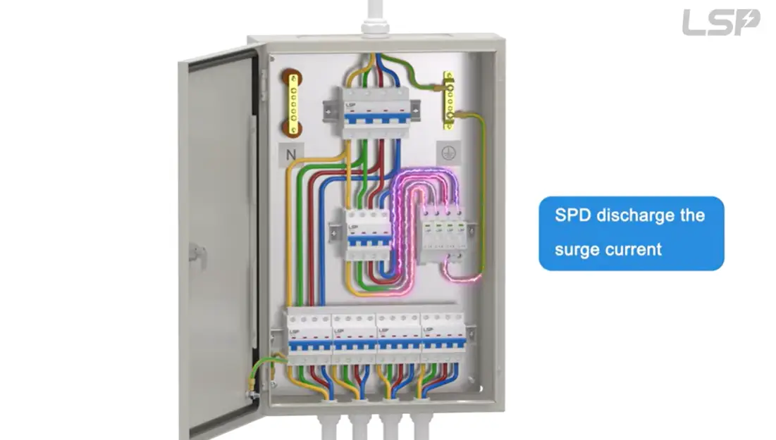
*This video discusses the basics of distribution boards and the calculations for electrical work in distribution board designs.
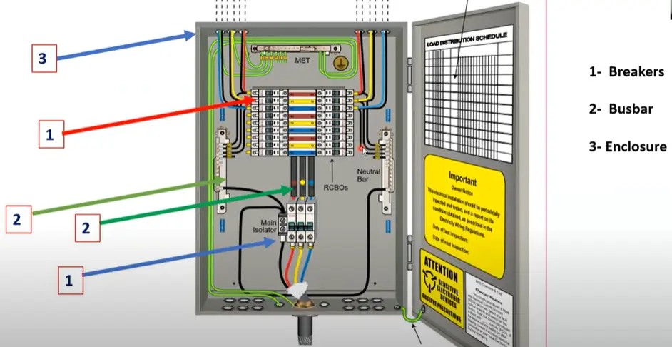
A distribution board is an enclosure or cabinet that contains the main safety devices and distribution elements of an electrical distribution system. It serves two purposes and is the classical foundation of electrical safety. Often, a facility will have a main distribution board (MDB) that feeds smaller sub distribution boards.
- First, it carries out Power Distribution. The primary power supply to a building, coming from the utility grid, is of high current rating and cannot be directly connected to end-use devices like lighting or sockets. The purpose of the distribution board is to use a central busbar to subdivide this main supply into several, lower-current branch circuits. These circuits are arranged to feed a particular area or type of load, allowing the wiring to be done systematically and manageably within the facility.
- Second, it offers Overcurrent Protection. The distribution board is fitted with protective devices like circuit breakers—such as miniature circuit breakers (MCBs) or moulded case circuit breakers (MCCBs)—to protect each sub-circuit. Each breaker is designed to automatically cut off the power supply if the current exceeds a safe level. This guards against two major dangers: an overload (where excessive current draw over a long period can cause wires to overheat and pose fire hazards) and a short circuit (where a fault causes a sudden, huge inrush of current that can destroy equipment and cause arcs). The main switch on the board allows for manual disconnection of the entire system.
These two functions are vital to any of the electrical systems it serves. However, in addition to overload and short circuits, the electrical grid has one more, less noticeable threat that cannot be covered by traditional protection methods: electrical surges.
The Hidden Threat: Why Surges Impact Your Design
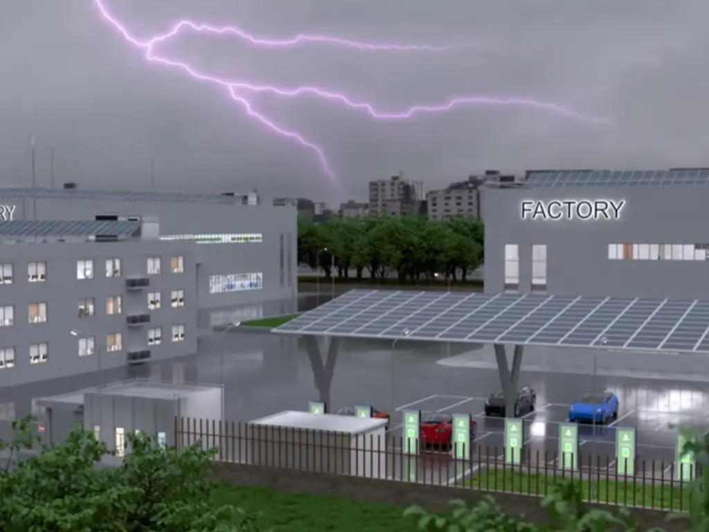
In order to develop truly reliable power distribution for complex electrical systems, contemporary design must consider transient overvoltages, also referred to as power surges. A surge is a very short and high-power change in voltage that can travel through an electrical system, potentially causing electric shock or equipment damage. The need to deal with this menace is driven by the fact that the nature of the loads and power sources connected to our systems is changing.
There are two primary power sources of surges:
- External Surges: Atmospheric events, mainly lightning strikes, cause the most powerful surges. A direct or nearby strike can impress huge temporary voltages onto the utility grid lines, which are then conducted into the building.
- Internal Surges: More common, but generally of lower magnitude, are surges produced inside the building or on the local power grid. Large inductive loads from heavy machinery—such as motors, elevators, HVAC systems (hvac), or welding equipment common in industrial applications—can cause large voltage fluctuations when started or stopped, impacting all other devices on the same network.
Previously, such events were not a major concern for the simple electrical and electronic devices in use. Nowadays, however, our offices, homes, and critical facilities like data centers are full of equipment built around sensitive microprocessors and electronic parts. Low, accurate voltages are used in computers, smart TVs, network routers, PLC controllers, and modern appliances. For such devices, a small surge lasting only microseconds can pierce fragile integrated circuits, causing instantaneous failure, power loss, or a slow degradation that reduces the equipment’s useful life.
Thus, the design of modern electrical distribution systemsmust consider surge protection as an equal requirement to overcurrent protection. Failure to do so exposes valuable and costly electronic assets to a predictable and ongoing risk of damage.
Integrating SPDs: The Third Pillar of Protection
Surge Protective Devices (SPDs) are one of the most critical safety features and the third essential element of modern electrical safety, alongside overcurrent protection (MCBs) and earth fault protection, provided by residual current devices (RCDs) or RCBOs. Incorporating them into a distribution board is a direct and effective action to protect against surge-related damage.
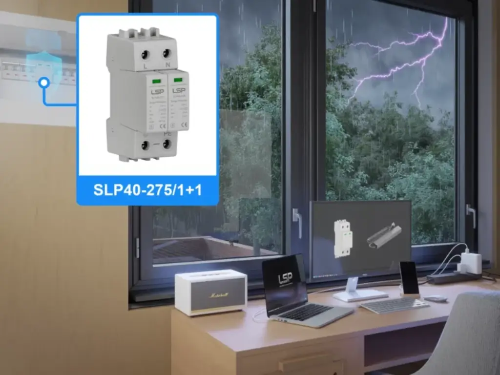
Installation Location of SPDs: To provide maximum protection for all downstream circuits, the SPD must be installed within the main distribution board at the point of entry. The best place is right after the main switch (main isolator or MCCB) and before the outgoing circuit breakers for the branch circuits. This positioning ensures that any surge entering the board via the main supply is redirected before it can spread into individual sub-circuits, thus safeguarding the whole installation.
The operation of SPDs in a DB: An SPD is a voltage-sensitive switch connected between the live conductors and the grounding (or earthing) system. Proper system bonding is crucial for its effectiveness. The principle of its work is simple:
- When the system voltage is at its proper level, the SPD has a very high impedance (resistance) in its normal state. It is electrically open and does not affect the normal functioning of the system.
- The internal components of the SPD instantly change to a very low impedance state when it senses a transient overvoltage (a surge). This provides a safe route for the excessive surge current to flow directly to the grounding system.
- The SPD clamps the voltage to a safe level by diverting the surge energy away from the protected circuits. When the surge is over and the system voltage has returned to normal, the SPD automatically returns to its high-impedance condition, ready to respond again.
This is a very rapid protective measure that takes place in nanoseconds and is very effective in protecting modern electronics against damaging voltage spikes.
A Step-by-Step Guide to Modern DB Design
A full and contemporary design process for efficient power distribution incorporates SPD selection into the conventional work flow. The four steps below, typically performed by a qualified electrician, provide for a safe, reliable, and resilient installation.
Step 1: Load Calculation & Circuit Planning
Start by determining all the electrical loads the distribution board will supply, whether from the grid or a backup generator. Calculate the total load capacity and current requirement of each circuit. Group loads in a rational way (e.g., lighting, general power, dedicated appliance circuits) and design the circuit layout to balance the load across the available phases. Importantly, always plan for excess capacity to accommodate future growth.
Step 2: Sizing Overcurrent Devices (MCBs/RCBOs)
For each planned sub-circuit, choose an overcurrent protective device (like an MCB, RCBO, or even older-style fuses) with a suitable current rating. The rating of the device should be selected to protect the circuit’s cable from overload. That is, it should not exceed the current-carrying capacity of the cable. Also, take into account the tripping curve of the device (e.g., Type B, C, or D) depending on the type of load to prevent nuisance tripping from inrush currents.
Step 3: Selecting the Right SPD
The selection of the SPD is based on the type of electrical system and the level of protection required.
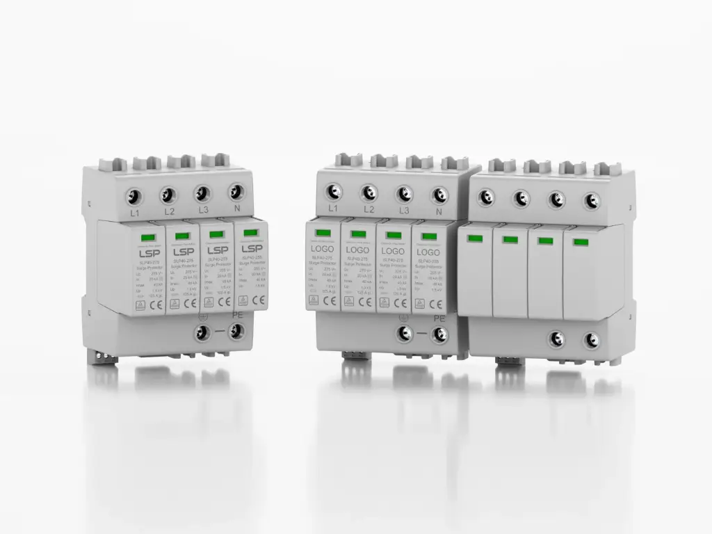
- SPD Type: A main distribution board would normally require a Type 1 or Type 2 SPD. A Type 1 SPD is installed where there is a high probability of a direct lightning strike (e.g., near the transformer), whereas a Type 2 SPD is the norm in most other installations to guard against induced surges. Type 3 SPDs are applied at the point-of-use for very sensitive equipment.
- System Configuration: The SPD must be compatible with the building’s groundingsystem (e.g., TN-S, TN-C-S, TT).
- Voltage and Parameters: Choose an SPD that has the rightvoltage rating for the system. Important performance parameters, which are discussed in the following section, should also be evaluated.
Step 4: Layout and Wiring
Draw a single-line diagram (SLD) of the distribution board that clearly indicates the main incomer, the SPD, all outgoing circuit breakers, and any other accessories. When physically wiring the board, the connection to SPD is critical. The leads between the SPD, live conductors, and the earth terminal should be as short and straight as possible. Long, looping wires add inductance, which increases the let-through voltage during a surge event and greatly diminishes SPD’s effectiveness.
Choosing a Reliable SPD for Your Design
Once the necessity and location of an SPD are determined, the final task is to choose a quality and reliable device. This choice must be based on technical specifications and confirmed safety standards.
Important Selection Criteria: When comparing SPDs, the following are important parameters to consider, all with the goal of ensuring stable electricity for downstream loads:
- Uc (Maximum Continuous Operating Voltage): The maximum voltage the SPD can continuously support without degrading. This should be greater than the nominal system voltage.
- In (Nominal Discharge Current): The highest current an SPD can sustain in a series of standardized impulses. It indicates the device’s durability and resistance to repeated surges, which is critical for industrial use.
- Imax (Maximum Discharge Current): The maximum peak current the SPD can survive in a single surge event without being destroyed. A larger Imax means a more robust device.
- Up (Voltage Protection Level): The residual voltage that passes through the SPD to the connected equipment during a surge. The lower the value of up, the greater the protection for sensitive electronics.
Certification: The certification of an SPD is crucial. It should be certified to international electrical standards, most likely IEC 61643-11 (for low-voltage power systems) or a regional equivalent like UL 1449. Third-party laboratory certification is a critical assurance that the device has been thoroughly tested and will operate as specified—a vital safety and performance guarantee. The physical enclosure of the device, sometimes made of materials like stainless steel for harsh environments, should also meet relevant standards.
LSP: Your Trusted Partner for Reliable Surge Protection
At LSP, we recognize that when designing an efficient distribution board, selecting the right SPD is essential to ensure long-term protection and optimal performance. Our SPDs are built to meet the highest industry standards, including TUV, CB, and CE certifications, ensuring safety and reliability for your projects. With high-quality LKD MOVs and Vactech GDTs, our devices provide robust protection against power surges, capable of handling up to 20kA discharge currents and designed for durability in demanding environments. Whether you’re working on a standard setup or need a tailored solution, LSP’s SPDs offer peace of mind, ensuring that your electrical installations are protected with top-tier surge protection technology.
Common Mistakes in Distribution Board Design
To ensure a safe and efficient power distribution system, it is important to avoid the most common design mistakes. These errors in contemporary design usually involve improper application or omission of surge protection.
Mistake 1: Total Omission of Surge Protection
- This is the greatest mistake in the contemporary context. It exposes all sensitive electronics in the installation to unavoidable power surges, causing premature failure and expensive replacements.
Mistake 2: Wrong SPD Location or Wiring
- Locating the SPD too far downstream or using connecting wires that are too long can render it ineffective. Wiringlength is a performance factor that must be kept to a minimum.
Mistake 3: Breaker and Cable Mismatch
- A classic but still common error is choosing a circuit breaker with a current rating too high for the cable it is meant to protect. This negates proper overload and short circuit protection and poses a severe risk of fire hazards.
Mistake 4: No Room for Future Expansion
- It is shortsighted to design a distribution board with no spare ways to add more circuits. This necessitates expensive and complicated changes when new loads are added later. Never plan for less than 20 percent spare capacity.
Conclusion: Redefining the Standard of Electrical Design
The contemporary distribution board should be considered a complete safety system—part of the larger switchgear infrastructure—rather than just a power distribution point. With the universal use of sensitive microelectronics, the use of Surge Protective Devices (SPDs) has become a design requirement, just as important as overcurrent (circuit breakers, fuses) and earth fault protection (RCD). This transition protects against the full range of electrical hazards, safeguarding not just property and people from fire hazards or electric shock, but also the vital and costly electronic devices that form the basis of contemporary productivity and everyday life.
As a result, the professional requirement for the design and installation of a power distribution system has become holistic. This involves careful planning, proper sizing of components, and the use of high-quality, certified devices in each protective role. Through the adoption of surge protection as an essential element and the strict observance of proper installation procedures by a licensed electrician, designers and installers can meet their obligation to provide genuinely safe, dependable, and robust electrical systems. This ensures reliable power distribution ready to face the demands of the modern technological environment.
At LSP, we offer a full line of IEC-compliant SPDs that are designed to provide the certified performance your projects require. With over a decade of expertise, we specialize in high-quality surge protection solutions that not only meet industry standards but exceed expectations. Whether for commercial or industrial applications, LSP’s products deliver dependable protection, helping you ensure safety and reliability in every installation. Let us help you uphold the high standards that modern electrical systems demand.