In an era where electronics are part and parcel of our day-to-day activities, the invisible threat of voltage spikes endangers a variety of equipment. The basic television set in a digital household and even the intricate control systems of a small firm rely on electrical power services within a delicate balancing act. This balance can be exceptionally disrupted by events as remote as lightning strikes or even the switching of electric loads within a building. The lack of adequate surge protection can have several consequences: appliances damaged beyond repair, operation of the business interrupted, and worse – safety risks. This is where single phasesurge protection comes in, quietingly standing guard to transient overvoltages. Learning about devices such as these, often referred to as surge protective device or spd, is more than an academic or technical task; it goes to the core of helping ensure reliability, functionality, and the prolongation of useful life of electrical systems and the various devices they service.
What Are Single Phase Surge Protectors?
Essentially, a single-phase surge protector, or SPD (Surge Protective Device), is an electrical device that protects equipment from damage caused by overvoltage conditions, commonly known as transients or surges. In contrast to the steady voltage typically supplied to devices, a transient voltage is a short, intense spike of energy. These electrical surges are brief—lasting only a few microseconds—but can inflict significant damage.
Single-phase systems are commonly used in homes and light commercial installations. These systems operate with alternating voltage delivered via a single-phase generator. A single-phase SPD is specifically designed to be installed in such systems to protect connected devices from surge-related damage. The primary function of an SPD is to divert excess surge voltage to the ground, ensuring that the voltage experienced by protected equipment does not exceed safe levels. These surge protectors function similarly to pressure relief valves in a plumbing system—quickly activating when excess “pressure” (voltage) builds up, thereby preventing damage.
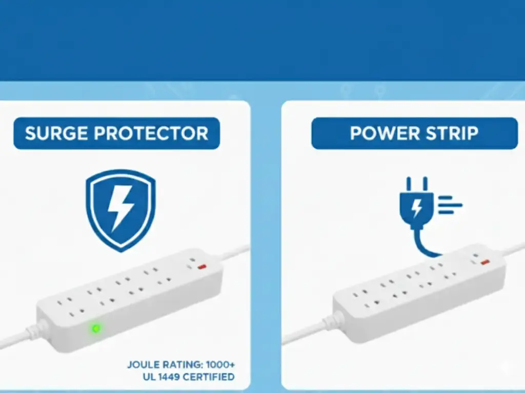
Unlike basic surge strips that offer limited protection, SPDs provide a much higher level of performance. While some power strips include basic surge protection components, single-phase SPDs are engineered to handle significantly greater surge voltages and currents and are built to stricter standards. They are typically installed at critical points in the electrical infrastructure—such as at the service entrance or within distribution boards—to ensure comprehensive protection and eliminate vulnerabilities, thereby providing effective AC surge protection for the system.
Why Single Phase Surge Protection Is Essential
Transient overvoltages, mixed with surge events and their threat, occur everywhere. Single phase surge protection is crucial. With multiple sources of lightning, single phase surge protection becomes imperative. Multi-voltage lightning strikes can generate massive voltage spikes, sometimes hitting structures situated several kilometers away. Apart from this, power surges can also be induced by the large switches rerouting power grid ports. Internal factors also play a part, such as inductive load switching and large industrial motor, which also increases the problem.
| Cause / Scenario | Impact / Risk | Importance of Protection |
| Lightning strikes (even miles away) | Generates large voltage spikes | Prevents high-energy damage to connected systems |
| Power grid switching operations | Induces surges during routine rerouting | Maintains stability during utility-side events |
| Industrial load switching (motors, inductive) | Internal surges created during machinery operation | Protects internal circuits and minimizes production downtime |
| External stray voltage/power anomalies | Damages sensitive modern electronics (computers, smart devices, etc.) | Shields devices like childcare systems, washing machines, and smart security components |
| Sensitive electronics (home or office) | Can be fried instantly, causing data loss or system failure | Reduces cost of replacements, IT repairs, and safeguards critical operations |
| Business reliance on networked systems | Sudden surges can halt productivity, cause data loss | Ensures business continuity and data integrity |
| Cumulative effect of small surges | Slow degradation of performance over time | Extends the lifespan of electronics and appliances |
| Home use (HVAC, appliances, entertainment) | Sudden loss of functionality, costly replacements | Enables whole-house protection, ensuring ongoing comfort and functionality |
Single phase surge protection should not be viewed as an unattainable luxury. Rather, it’s a fundamental protective measure directed at enhancing asset value in industrial plants with surge powered single phase electrical systems while ensuring operational continuity. In an effort to protect electrical assets, single phase surge protection aids in returning the investment by preventing costly damages while maintaining infrastructure dependability.
The Core Principle: How Single Phase SPDs Work
The core working principle of a single phase Surge Protective Device (SPD) lies in its ability to change its electrical impedance almost instantaneously in response to changes in voltage. Under normal operating conditions—when, when the voltage remains within safe, acceptable limits—the SPD maintains a very high impedance. In this state, it behaves much like an open circuit, meaning it has no impact on the normal flow of electric current and does not interfere with power consumption by connected equipment.
However, when a transient overvoltage or surge occurs—exceeding a specific threshold known as the clamping voltage—the SPD responds immediately. Its internal components shift from high to low impedance, allowing surge current to flow through the SPD rather than passing through and damaging sensitive downstream equipment. This sudden shift enables the SPD to act as a preferred pathway for excess energy, safely diverting it away from critical systems.
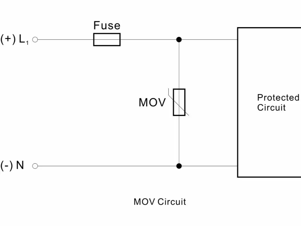
This dynamic response is made possible by non-linear, voltage-dependent components within the SPD. Common technologies used include Metal Oxide Varistors (MOVs), which sharply decrease in resistance when exposed to high voltage, allowing them to conduct surge current effectively. Other elements such as Gas Discharge Tubes (GDTs) and Silicon Avalanche Diodes (SADs) are also used depending on the application, each bringing specific characteristics to enhance protection. Once the surge subsides and normal voltage resumes, the SPD components return to their high-impedance state, restoring the device to standby mode. This swift, automatic mechanism is essential to steer damaging currents away and cap the voltage to safe levels, ensuring reliable protection for electrical systems.
Understanding SPD Types: Type 1, Type 2, and Type 3
Since not all surge protection requirements are the same, SPDs are grouped into different classes based on their purpose, geographical placement, and the amount of surge energy they can handle. The most common classification divides SPDs into Type 1, Type 2, and Type 3, which are frequently utilized within a coordinated surge protection scheme.
| SPD Type | Placement | Surge Protection Capability | Surge Waveform Tested | Common Use Cases |
 Type 1 | Service entrance (before main overcurrent protection) | Highest protection, handles very high-energy surges (e.g., direct lightning strikes) | 10/350 µs (simulates direct lightning strike) | Whole house or entire building protection, especially for lightning strikes and powerful external surges |
 Type 2 | Main distribution panel or sub-panels | Protects against residual surges from Type 1 and internal surges caused by switching events | 8/20 µs (lightning-induced surges, weaker than direct strikes) | Most commonly used in homes and commercial properties to protect wiring systems and equipment |
 Type 3 | Point-of-use (near protected equipment) | Mitigates residual voltage and localized surges from equipment or nearby sources | 1.2/50 µs (combination voltage) and 8/20 µs (surge current) | Surge protector power strips, built-in electronics, supplementary protection for Type 1 and Type 2 devices |
Using multiple classes of SPDs placed in different locations in the electrical system is the best approach to defend against any surge event, offering layered, reliable surge protection.
Deciphering the Standard Single Phase SPD Wiring Diagram
Comprehending the wiring of asingle-phase SPD is essential for proper installation and reliable surge protection downstream of the main breaker. While specific wiring diagrams may vary slightly between SPD manufacturers and models, the basic electrical connections in a single-phase system – live (L), neutral (N), and protective earth (PE) – are generally consistent.
In the case of a simple single phaseSPD which is connected in parallel with the electrical load as most commonly configured, the wiring is done at the protection terminals. The SPD will have terminals or leads labeled as connecting to live, neutral and protective earth ground.
In the standard wiring schematic:
- A wire is run to the live (L) terminal of the SPD from the live conductor of the circuit.
- A wire is run to the N terminal of the SPD from the neutral conductor of the circuit.
- A wire is run from the protective earth busbar or terminal to PE terminal of the SPD.
This parallel connection guarantees that the current continuously flows to the connected equipment under normal voltage conditions. Surge currents, on the other hand, will use the SPD’s low impedance path between L-PE, N-PE, or in some cases L-N to be bypassed to earth ground without going through the equipment, offering critical ac surge protection.
Conclusion
It is extremely important that the connections are made with conductors which are properly sized, as short and as straight as possible. With SPDs, efficiency can be affected greatly by the length and routing of the connecting wires or wiring. Coiled or longer wires can introduce inductance that may delay the diversion of surge current. This can increase the rapid diversion of surge current and result in a higher let-through voltage (the voltage that still reaches the equipment). To better understand, consider trying to drain water quickly through a long winding hose versus a straight pipe. The latter is more efficient.
Most SPDs have internal disconnects or externally connected overcurrent protection (fuses or circuit breakers). This is crucial for safety; in case of any internal failure, the SPD will be isolated from the circuit as well as in the case of a very large surge exceeding the device’s capacity. The wiring diagram will show how this disconnect control is incorporated into the circuit. It is always important to follow the manufacturer’s wiring instructions and specific diagrams for the chosen SPD to ensure safe and proper installation.
Wiring Different SPD Types by Location (Type 1, 2 & 3)

Surge protection is effective only when the correct SPD type is installed at the proper location. Using Type 1, 2, and 3 SPDs in a cascaded setup offers the best system-wide protection.
- Type 1 SPD Wiring: Type 1 SPDs serve as the first line of defense against external surges, such as direct lightning strikes. They should be installed at the service entrance of the building, typically at the main distribution board. These devices are often connected to the flow side of the primary incoming fuse or circuit breaker (main breaker). The SPD is wired to the incoming live conductor(s), the neutral conductor, and the main protective earth terminal (earth bar). The purpose of Type 1 SPDs is to suppress large surge currents, preventing them from traveling throughout the building’s wiring system and thereby protecting the entire structure. Due to the high energy levels involved, the conductors connected to Type 1 SPDs are typically heavy-duty, short, and direct to minimize impedance.
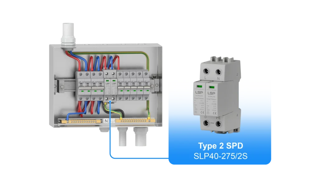
- Type 2 SPD Wiring: Type 2 SPDs are installed at the primary distribution board in installations without external lightning protection or downstream from Type 1 SPDs (if present). They protect against internal transients and induced surges. Type 2 SPDs are connected to the live, neutral, and protective earthing conductors of the distribution board or sub-panel. They are typically wired in parallel to the circuit breakers or fuses that protect the downstream circuits, ensuring that surge energy is directed to the earth busbar. Type 2 SPDs are essential for most indoor surge protection systems and provide whole-house surge protection.
- Type 3 SPD Wiring: Type 3 SPDs are installed at the point of use, providing localized protection for sensitive equipment. They may be integrated into power outlets, hardwired directly to specific equipment, or installed as plug-in surge protectors. Type 3 SPDs connect to the live, neutral, and earth conductors of the specific circuit or outlet supplying power to the equipment. While their surge handling capacity is lower than that of Type 1 or Type 2 SPDs, their close proximity to the equipment provides effective protection against residual voltage or transients. It is important to note that Type 3 SPDs are most effective when used in conjunction with upstream Type 1 or Type 2 protection. Relying solely on Type 3 SPDs for a whole-house system leaves the installation vulnerable to large, high-energy surges.
Appropriate coordination of these types of SPDs with their respective wiring at each location creates an increase in the operational capability of some system parts while restraining others. This, in effect, gradually reduces surge magnitude in its path through the electrical system, protecting sensitive equipment, not just the most, providing reliable surge protection.
Common Installation Challenges and Mistakes to Avoid
*To help illustrate this more clearly, we’ve put together a video for you.
When installing single-phase surge protection devices (SPDs), there are some unique problems and oversights that, if not handled correctly, can disrupt the proper functioning of the device. While the task may seem simple, SPDs that are not installed properly or safely can pose a grave threat. Certain rules must be followed and common installation mistakes should be avoided to provide optimal surge protection. Below are some suggestions to help guide you avoid mistakes in the installation of SPDs.
Guidelines for Surge Protectors Oversight
- 50-Centimeter Rule:The ’50-centimeter rule’ is a general guideline for how long a cable should be between a single-phase surge protector and the mains network. Overlong cables might damage loads. Inductance increases under fast rise time conditions, causing high transient voltages to accumulate in long cables. Indeed, the shorter the connection, the more effective the protection. More than any other parameter cable length determines a surge protector’s ability to dissipate overvoltage up to a given value.
- 10-Meter Rule: If they are longer than 10 meters, install a second surge arrester as close to the equipment as possible. Use the same surge arrestor brand and follow the manufacturer’s coordination table.
- Location of the SPD: In order to limit overvoltages as much as possible, note that the first level of surge protection device must be installed as far upstream as possible of the installation in order to reduce as much as possible the induced effects of the lightning by electromagnetic coupling. Don’t forget about it. Transients can enter a building or facility via phone lines, computer networks, CCTV systems, and any other means. Install single-phase surge arrestors on any device or system that is vulnerable to overvoltage.
- Coordination with Circuit Breakers: If the surge protection device exceeds its limitation capacity, it may be destroyed by short-circuiting itself. Coordination between a surge protective device and its circuit breaker (or fuse) is therefore critical in an electrical system.
- Compliance with the Earthing System: It is essential to check that the surge protection devices used are compatible with the earthing system
Errors to Avoid
- Disproportionate Grounding: One of the most widespread blunders is disproportionate grounding. Effective surge current flow requires a good ground connection. Disconnecting the SPD from a low impedance ground leads to SPD failure and damage to associated equipment. Grounding shortcomings include inadequate conductor dimensions, degraded electrodes, or poor electrodes. Grounding as a whole is foundational to surge protection and if improperly executed, will compromise the system.
- Excessive Cable Lengths: The connecting cables between the SPD and the electrical panel or equipment need not be long. Having longer cables poses a bigger challenge profile. For example, longer cables will have increased impedance which will lead to increased let-through voltage with a greater impedance. For optimal SPD effectiveness, let wiring be short and direct.
- Selecting the Wrong SPD Type or Rating: Opting SPD of the wrong type, or surge current rating could be catastrophic. For instance, putting in a Type 3 SPD at the service entrance will most certainly lead to insufficient protection from lightning-induced surges. Pay attention to the selection of SPDs as per their exposure and make sure surge current values are set right.
- Lack of Overcurrent Protection: Overcurrent protection is absent in some bundled SPDs. But basic protection is found in internal safeguards such as fuses or circuit breakers. If an SPD fails without overcurrent protection, it becomes possible to short circuit or set fire. Therefore, proper selection and coordination with the SPD is critical when confirming overcurrent protection.
- Common Wiring Problems: Not identifying and connecting live, neutral, and earth conductors correctly is a frequent oversight. Furthermore, various earthing configurations (such as TN, TT, IT systems) dictate how the SPD should be affixed and wired. Misinterpreting the system can lead to improper wiring, which may cause the SPD to be useless.
Following the common mistakes mentioned above along with the specific rules while installing the SPDs will ensure reliability and effectiveness in the protection offered by Single-phase surge protection devices. The effectiveness of surge protection is bound to its most vulnerable point which, more often than not, is the installation. Understanding SPD technology and installation intricacies, coupled with the involvement of a professional electrician, can mitigate such blunders.
Best Practices for Single Phase SPD Installation Wiring
To optimize the safety and effectiveness of single phase SPD installations, following best practices SPD design integration approaches is important. These practices facilitate surge path impedance, coordination, and safety for ac surge protection.
- Prioritize Short and Direct Connection: This is arguably the most significant short and direct connection best practice. The SPD wires to live, neutral and earth points should be as straight and short as possible in the wiring. A straight route that minimizes bends is ideal. Reducing bend increases surge path inductance. Surge current diversion will happen faster, and equipment let-through voltage will significantly drop, leading to more reliable surge protection.
- Select Correctly Sized Conductors: Connecting wires that SPD manufacturers suggest should not have too small a diameter since they have high impedance which can cause overheating and excessive impedance. Relevant electrical codes, such as those referenced by UL or NEMA, should be followed for appropriate ampacity. Reduction of conductivity increases bottleneck, surge path reduced effectiveness.
- Make Sure There is A Robust, Low Impedance Earth Ground Connection: The connection allows for diversion of surge energy, or surge current. A superb ground earthing link is vital for any surge protection device. Check that the ground electrode system complies with the relevant codes as does the ground connection to the SPD earth terminal, since it need be strong with low resistance. Ground straps, connectors are to be periodically checked and maintained.
- Coordinate the Various Types SPD: For integrated whole house or entire homeprotection, apply a coordinated method with Type 1 and Type 2 and perhaps Type 3 SPDs at different locations. This multi-tiered approach allows for more sensitive equipment to progressively counteract increasingly lower surge energy levels. Be certain that energy coordination among the different types SPDs is adopted according to the manufacturer’s instructions for reliable surge protection.
- Integrate Proper Overcurrent Protection: The SPD should always be paired to an adequately rated fuse or circuit breaker. This protective device must be located as close as practical to the cooldown monitor/socket where the SPD‘s access to the circuit is. This avoids harm to the circuit and reduces the risk of firefighter represent burns when dealing with SPD failure or surge. This typically involves a specific breaker or fuse size.
- Properly Mount SPDs: As per the manufacturer’s mounting instructions, install SPDs in their proper enclosures or within electrical panels. Ensure there is ventilation, if needed, and prevent the SPD from being physically damaged or exposed to environmental elements.
- Label and Document: Clearly label the installed SPD with its type, rating, and the protected circuits. Keep paperwork for the installation, including schematic drawings of the wiring and product details. This information is extremely important for future maintenance, troubleshooting, and inspections of the surge protection device.
- Regular Inspection and Testing: SPDs have a limited lifespan and may have a lower performance capacity as they age, especially after multiple surge diverting events, impacting reliable surge protection. Therefore, implement regular visual inspection schedules and, if applicable, check indicator status. Consider scheduled checkpoints with a qualified professional to verify the SPD still functions as intended and provides the expected level of protection.
With the diligent adhering to these practices, installers fortify single phasesurge protection system’s reliability and effectiveness while shielding against overvoltages using a robust protective device.
Ensuring Safety and Compliance: Standards and Regulations

The installation and operation ofsingle-phase surge protection devices (SPDs) are governed by a comprehensive set of safety, reliability, and performance standards. Adhering to these standards is not only considered best practice but is often a legal requirement in AC surge protection applications. Internationally recognized standards ensure SPDs are designed and tested to meet specific safety and effectiveness criteria. The IEC 61643 series, established by the International Electrotechnical Commission, is widely adopted for low-voltage surge protective devices. Part 11 of this series specifically covers SPDs connected to low voltage power systems, defining performance and test requirements for Type 1, Type 2, and Type 3 devices.
Products that carry certifications such as ISO 9001, TÜV, CB, and CE demonstrate conformity to international quality management and electrical safety standards. ISO 9001ensures consistent production and quality control processes, while TÜV certification signals compliance with rigorous German and international safety standards. The CB Scheme provides mutual recognition of test results among member countries, and CE marking indicates that the product meets EU safety, health, and environmental protection requirements. These certifications give end users and regulatory bodies confidence that the SPD has been evaluated for reliability and performance under recognized testing procedures.
In addition to product certifications, national electrical codes such as the National Electrical Code (NEC) in the United States—specifically Article 285—define how SPDs should be applied and installed, including rules on conductor sizing and overcurrent protection. Such codes help prevent SPD failure that could lead to electrical fires or system damage. Compliance with these standards is essential not only for ensuring safe and effective installations but also for passing inspections, securing permits, and obtaining insurance. Ultimately, all stakeholders involved in specifying, installing, or maintaining SPDs must understand and follow relevant standards and laws, applying correct guidelines for AC systems and voltage ratings. This is particularly true for industrial applications requiring a 3 phase surge protection device, helping to achieve responsible and compliant electrical system design.
Ensuring Connection Reliability – Why LSP Surge Protectors Make the Difference
Now that we’ve covered how to wire a single phase surge protector correctly, the next important step is choosing a reliable and high-performance SPD. At LSP, we’ve been specializing in surge protection devices since 2010, with products exported to over 10 countries. Our factory is ISO9001-certified and our SPDs meet international standards including TUV, CB, and CE. With over 15 years of expertise, we provide trusted solutions for residential, commercial, and industrial applications—making LSP an ideal choice for your wiring projects.
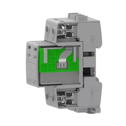
LSP’s single phase SPDs are designed for full compatibility with both 3+1 and 4+0 wiring configurations, meeting the requirements of European and global standards. Whether you’re connecting L-N or N-PE paths, our devices include critical safety and performance features like encapsulated MOVs to resist moisture, internal thermal disconnection to prevent fire risk, and built-in indicators with remote signaling. These features not only make installation straightforward, but also ensure consistent protection and peace of mind long after the wiring is complete.
If you’re currently selecting an SPD for your single phase system or finalizing your wiring layout, LSPoffers more than just hardware. We support custom branding, packaging, and certification services to fit your project requirements. Our team also provides expert technical advice and sample units to help you evaluate performance before deployment. After reviewing this wiring diagram guide, we invite you to explore LSP’s single phase surge protectors—engineered for safety, built for long-term reliability.