Terminology in the exact field of electrical engineering and power distribution is not a semantics issue; it is the basis of safety, compliance, and system reliability. Although they have similar functionality in the regulation of the flow of electricity, their assigned functions, technical capabilities, and physical structure are entirely different.
This guide will give a conclusive description of the major differences between these two important elements of an electrical distribution system. We shall proceed beyond basic definitions to a detailed technical comparison, the ubiquitous menace of power surges, and a strategy to protect systems. The aim is to provide engineers, facility managers, and electrical equipment distributors with the exact knowledge needed to design, specify, and maintain electrical installations that not only work but are also extremely safe and robust.
Why This Distinction Is Critical for Your Electrical System’s Safety
The use of distribution board and switchboard interchangeably ignores the basic principles of design and is a direct risk to safety, compliance, and operational stability. The repercussions of ordering the wrong equipment are dire.
Safety-wise, the installation of a distribution board in a high-energy area that requires the strength of a switchboard has the potential to result in a catastrophic failure due to fault currents, resulting in arc flash and fire. Regarding compliance, every part should comply with different regulatory requirements (e.g., switchboards should be compliant with UL 891, distribution boards with UL 67). Non-compliance leads to expensive rework, project delays, and high legal liability.
Lastly, there is operational and financial stability at risk. One component used in the wrong way can lead to the collapse of the whole system and costly downtimes. Although over-engineering is a waste of capital, under-engineering results in early equipment failure and a reduced system lifecycle. This is the fundamental difference that must be understood as the first step in engineering a safe, compliant, and reliable electrical system.
Defining Their Roles in the Power Distribution Hierarchy
In order to understand the functional difference between a switchboard and a distribution board, it is first necessary to imagine the structure of a power distribution system. This is a hierarchical network system that is intended to safely and efficiently step down high-capacity electrical power of a utility source to the usable energy that supplies individual appliances and equipment. The switchboard and distribution board have different and consecutive places in this hierarchy.
The Switchboard: The Primary Power Distribution Hub
The main point of the electrical distribution system is the switchboard. It is usually the first equipment to be connected after the primary power source, e.g., the utility service entrance transformer or a large-scale generator. Its primary task is to accept the primary incoming power feed, a high-current, high-capacity electrical supply, and split it into smaller, more manageable units of power.
This main distribution center controls the mass flow of electricity in a whole facility or a major part of it. A switchboard is designed to carry high electrical loads and may be rated to 6000 amperes or higher. It has large protective circuit breakers or fuses that supply other downstream switchboards, large motor loads, and most often, several distribution boards distributed throughout the facility. Because of its involvement in controlling the primary source of power, it is nearly always housed in a special, secure electrical room with restricted access.
The Distribution Board: The Secondary Power Distribution Node
The next level down in the hierarchy of power distribution is the distribution board, sometimes called a panelboard or breaker panel. It acts as a secondary distribution point and is fed by an upstream switchboard with electrical power.
The main role of a distribution board is to accept the bulk power fed to it and then further subdivide it into smaller subsidiary circuits or branch circuits. These are the last circuits that feed directly to lighting, receptacles, small motors, and other appliances in a given area, e.g., a floor in an office building, a section of a factory, or a wing of a hospital. A distribution board is basically the last point of control prior to the distribution of power to the end-use loads. It has a much lower rating than a switchboard, and is usually not more than 1200 amperes. One or a small number of main switchboards will be found in a single facility, but there will probably be tens or even hundreds of distribution boards that control the different circuits around the property.
Basically, the switchboard is used to distribute electric power wholesale, and the distribution board is used to distribute electric power to the end points of use.
The Technical Breakdown: A Head-to-Head Comparison
Although their hierarchical functions determine their purpose, a closer look at the technical specifications will show the underlying engineering differences that make each component fit its particular purpose. These variations include standards of governance, electrical power, fault tolerance, and physical design.
Key Specifications at a Glance
A direct comparison highlights the distinct design and performance characteristics of each component. The following table provides a clear, side-by-side view of their core specifications.
| Feature / Specification | Switchboard | Distribution Board (Panelboard) |
| Governing Standard (UL) | UL 891 | UL 67 |
| Maximum Current Rating | Typically up to 6000A or higher | Typically up to 1200A |
| Busbar Bracing | Individually braced and supported | Housed within a molded case assembly |
| Physical Footprint | Large, freestanding enclosure | Compact, wall-mounted or flush-mounted |
| Installation & Access | Floor-standing; requires front and often rear access | Surface or flush-mounted; requires front access only |
| Circuit Breaker Types | Can accommodate large, individually mounted, draw-out, or bolt-on breakers | Primarily uses smaller, plug-in or bolt-on molded case circuit breakers (MCCBs) |
| Typical Application | Main service entrance of industrial facilities, large commercial buildings, and data centers | Sub-distribution for lighting, receptacle, and appliance branch circuits |
Fault Current Withstand Capacity: The Critical Safety Metric
The Fault Current Withstand Capacity, commonly referred to as the Short Circuit Current Rating (SCCR) is perhaps the most important technical differentiator. Simply put, SCCR is the highest amount of fault current that a component can safely handle without a catastrophic failure, e.g., explosion or fire.
The required SCCR depends on the location of the component in the electrical distribution system. A switchboard is normally placed very near the main power source (the utility transformer,) where the available fault current is very high. Switchboards are therefore designed with heavy busbar systems, heavy-duty enclosures, and heavy bracing to safely handle these enormous forces, and may have an SCCR of 200,000 amperes or more.
The upstream circuit breaker in the switchboard and the impedance of the feeder cables protect a distribution board, which is further downstream. This implies that the fault current available at its point is much less. Consequently, it is not as well built and its SCCR is also lower, usually between 10,000 and 65,000 amperes.
Installing a distribution board having a 22,000A SCCR in a place where the available fault current is 85,000A is a direct contravention of the electrical code and a disaster waiting to happen. The board could not possibly hold the huge magnetic and thermal energy of a short circuit, resulting in a violent failure. That is why the fault current analysis is an obligatory procedure in the design of a safe power distribution system and in choosing the proper equipment.
Construction & Accessibility: Design for Different Purposes
The physical construction and accessibility of switchboards and distribution boards are direct reflections of their intended roles and the equipment they house.
Switchboard Construction
A switchboard is built as a freestanding, large assembly, usually composed of several vertical parts bolted together to create one rigid chassis. This modular design can be customized to a high level to suit individual metering, controls, and circuit protection needs. The enclosure is made to be durable and nearly always floor-mounted.
Importantly, most switchboards are front-access and rear-access switchboards. This is because they accommodate large, individually mounted circuit breakers and complicated busbar systems, which need a lot of space to install and maintain. An electrician might want to reach the back of the building to safely connect or service parts. This need determines bigger electrical room footprints to be able to have safe working clearances.
Distribution Board Construction
Conversely, a distribution board is a much smaller, self-contained device contained in one common enclosure. It is space-saving and is normally mounted on a wall (surface mount) or in a wall (flush mount).
The inside is configured to a greater concentration of smaller branch circuit breakers, frequently fitted on a standardized DIN rail or inserted into a vertical busbar system. All wiring, installation, and operation are frontal. Such a front-access-only design allows distribution boards to be fitted in electrical closets or on walls in the public areas without needing rear clearance, and thus they are ideal for sub-distribution in the various circuits within a building.
The Unseen Enemy: Why Both Boards Are Prime Targets for Power Surges

Once a facility has been properly designed with the proper switchboards and distribution boards, it is still susceptible to a ubiquitous and devastating threat: transient overvoltages, otherwise referred to as power surges. Such incidents are a major contributor to equipment damage and operational downtime, and both switchboards and distribution boards are major points of impact.
A power surge is a sudden and intense increase in the voltage of the electrical system. These rushes have two main sources:
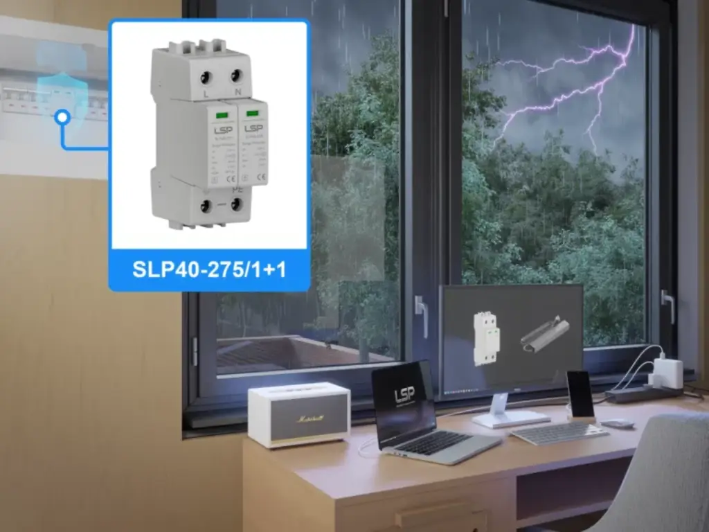
1. External Sources: Lightning strikes can cause the most powerful and destructive surges either by direct hit on the facility or more often by striking utility lines in the area. Such events can inject millions of volts and thousands of amperes into the electrical system within microseconds.
2. Internal Sources: More common, but generally less intense, surges are produced inside the facility. Voltage spikes are generated when large inductive loads (motors, HVAC systems, and welding equipment) are started and stopped, and these spikes travel across the local network. The net result of these smaller, repetitive surges may deteriorate and eventually destroy sensitive electronic components.
The switchboard and distribution board are particularly susceptible since they are the focal points of the power network. The main switchboard is the first point of entry of all external surges into the facility. In the absence of proper protection, a surge caused by a lightning strike will go straight through the switchboard and be shared out to all the downstream circuits.
At the same time, internally generated surges are concentrated at distribution boards. A surge on one branch circuit caused by a large motor can bounce back to the distribution board and extend out to all other subsidiary circuits on the same panel. This exposes sensitive equipment such as computers, control systems (PLCs), and communications hardware to a continual threat, even when the surge-generating equipment is in another part of the building. The difference between consumer unit and distribution board further explains exposure pathways for sensitive electronics. The outcome is failure of equipment, corruption of data, and expensive disruption of business processes.
The Solution: How LSP SPDs Provide Total Protection
The Surge Protective Device (SPD) is the key element in defense against this invisible enemy. An SPD is a device that is used to sense a transient overvoltage and, in nanoseconds, redirect the dangerous excess current to the ground safely and protect all downstream equipment. The installation of SPDs is not a choice anymore but a basic need to create a robust and stable electrical system.
The success of this protection, however, is solely based on the quality and the technological advancement of the SPD itself. The essence of the performance of SPD is its internal technology and manufacturing quality. In order to work, an SPD should be constructed using quality materials and a strong design that can resist tremendous electrical stress.
This is where the benefit of a special manufacturer such as LSP can be seen. The effectiveness of an SPD is predetermined by a number of factors:
- Core Components: The main protective elements are usually Metal Oxide Varistors (MOVs) or Gas Discharge Tubes (GDTs). The SPD clamping voltage (the voltage at which it begins to shunt current) and its energy absorption capability depend on the quality of these components. An example of this is LSP, which uses high-quality MOVs and GDTs that are the same as those used by the leading brands in the world, and guarantee a quick and efficient protective reaction.
- Safety Features: The end-of-life behavior of the SPD is a critical, but frequently ignored, feature. Repeated surges can degrade an MOV. An SPD with a safe disconnection mechanism should be well designed. The proprietary internal thermal disconnection system developed by LSP during a three-year intensive research guarantees that a failed SPD module is safely disconnected from the electrical system. This is a very effective way of extinguishing the arc, so that the SPD itself does not become a fire hazard, which is an important safety aspect that is confirmed by complete TUV, CB, and CE certifications.
- Durability and Construction: The machine has to be durable. Enhanced, flame-retardant housing materials (such as PA6+GF30%) and extremely thick, corrosion-resistant metal connectors (which have been tested in 48-hour salt spray tests) make the SPD able to survive in harsh industrial conditions. It is this dedication to quality construction and material that allows a manufacturer to provide a 5-year warranty, a sure sign of reliability that is far beyond the industry standard of two years.
Strategic Defense: Applying Coordinated Protection (Type 1 & 2 SPDs)
A single SPD is not enough to provide full protection. An effective strategy is a multi-level approach that is coordinated and is called cascaded or coordinated surge protection. The approach involves the application of various forms of SPDs at various locations within the power distribution network to make sure that harmful surges, whether of any source or level, are alleviated.
This method is accepted by standards organizations such as the IEC and is essential to the protection of sensitive electronics in contemporary facilities.
Type 1 SPDs: First Line of Defense
The first line of defense in the facility is a Type 1 SPD. It is mounted at the service entrance, usually in the main switchboard or just upstream. It is designed to absorb the enormous amount of energy of external surges, namely the high-energy waveform of a direct or nearby lightning strike (a 10/350us waveform). A Type 1 SPD redirects most of this destructive energy at the point of entry, and this saves the infrastructure of the entire electrical system against catastrophic damage.
Type 2 SPDs: Second Line of Defense
The second line of defense is a Type 2 SPD and is fitted in downstream distribution boards or sub-panels. It serves two purposes: to intercept any remaining surge energy that the upstream Type 1 device has passed; and second, and more commonly, to intercept surges that have been generated internally within the facility. These SPDs are tested using a different waveform (an 8/20us waveform) that is representative of these lower intensity but much more frequent surge events. Locating Type 2 SPDs in distribution boards that supply critical loads such as control panels, IT closets, or sensitive manufacturing equipment, you will achieve a localized protection level that is critical to the reliability of operations.
LSP as a specialist SPD manufacturer, offers a full range to apply this coordinated protection strategy. These are high-quality Type 1 devices to the main switchboard, high-performance Type 2 devices to distribution boards, and new hybrid Type 1+2 devices that provide a compact solution to some applications. This ability, along with the experience in creating solutions to challenging industries, such as photovoltaic systems, 5G telecommunications, and data centers, enables the creation of an optimal protection scheme of any facility. Moreover, the OEM/ODM services allow the smooth incorporation of these protective devices into the designs of panelboard and switchboard manufacturers.
Quick System Health Check: Is Your Facility Truly Safe?
An electrical system that is functional is not necessarily safe and resilient. In order to assist you in determining the health of electrical protection in your facility, perform this simple assessment. A response to no to any of these questions can be a sign that your system has a serious weakness.
1. Does your main service entrance or switchboard have a properly rated Type 1 SPD? In its absence, your whole facility is vulnerable to the full blast of external surges such as lightning.
2. Do distribution boards supplying sensitive or critical loads (e.g., servers, PLCs, automated machinery, communication equipment) have Type 2 SPDs? Internal surges are always a threat, and point-of-use protection is necessary.
3. Are the visual status indicators on your installed SPDs clear and functional? An unsuccessful SPD does not protect. An obvious sign (e.g., green good, red replace) is essential to maintenance in time.
4. Do your SPDs have an independent testing laboratory certification, such as TUV, CB, or UL, that is globally recognized? The only objective evidence that a device has passed critical safety and performance requirements is certification.
5. Does your existing SPD provider provide a warranty longer than the industry standard of two years? A longer warranty (e.g., 5 years) is a strong indicator of the manufacturer’s confidence in their product’s durability and long-term reliability.
6. Does your protection strategy consider all power systems, such as both AC and DC circuits, in niche applications, such as photovoltaic (PV) or energy storage systems (ESS)? Such systems possess special protection needs that should be met.
Conclusion: From a Functional System to a Resilient Fortress
The difference between a switchboard and a distribution board is central to the safe and rational design of any electrical system. Proper utilization of these elements according to their technical abilities and ranks is the foundation of a sound installation.
But in an age of sensitive electronics and the high cost of downtime, a functional system is no longer adequate. A proactive approach is required to safeguard that system against the ever-present and invisible danger of power surges, as true resilience requires. This protection is not an incidental benefit or a cost of doing business; it is a fundamental investment in the long-term viability and profitability of your business.
With a coordinated surge protection strategy, you put your electrical system on steroids, turning it into a fortress, by installing expertly designed, certified SPDs at strategic locations within your power distribution system. This is a way of protecting your critical assets, safeguarding your personnel, and ensuring the future of your operations against a volatile electrical environment.
Contact the professionals at LSP to schedule a free professional consultation to make sure your facility is completely covered with a state-of-the-art surge protection solution that fits your specific needs.